Manuals
/
Emerson
/
Computer Equipment
/
Power Supply
Emerson
UPS Systems Cabinet-to-Cabinet, Bolting Instructions, A Detail A, Installation Drawings
Models:
UPS Systems
1
29
36
36
Download
36 pages
16.53 Kb
26
27
28
29
30
31
32
33
<
>
Specifications
Install
Warranty
Safety
AC Power
Page 29
Image 29
Installation Drawings
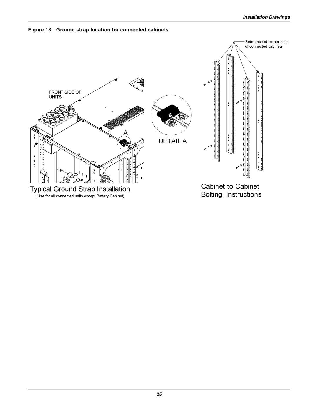
Figure 18 Ground strap location for connected cabinets
Reference of corner post of connected cabinets
FRONT SIDE OF
UNITS
A
DETAIL A
Typical Ground Strap Installation
Cabinet-to-Cabinet
Bolting Instructions
(Use for all connected units except Battery Cabinet)
25
Page 28
Page 30
Page 29
Image 29
Page 28
Page 30
Contents
Installation Manual - 250-400kVA, 60Hz
Liebert NXL Maintenance BypassCabinet
AC Power
For Business-Critical Continuity
CONTACTING LIEBERT FOR SUPPORT
Product Warranty Registration
1.1 Introduction 1.2 Preliminary Checks
TABLE OF CONTENTS
1.3 Environmental Considerations
1.4 Positioning
TABLES
FIGURES
SAVE THESE INSTRUCTIONS
IMPORTANT SAFETY INSTRUCTIONS
1.1 Introduction
1.0 SINGLE-MODULE MECHANICAL INSTALLATION
1.2 Preliminary Checks
1.3 Environmental Considerations
1.4 Positioning
1.4.3 Floor Installation/Anchoring
1.5 Cable Entry
1.3.2 Storage
Liebert
1.6 Power Cables
Liebert
Liebert
Equipment Ground
1.6.1 Power Cable Connection Procedure
The grounding and neutral bonding arrangement must be in accordance with local and national codes of practice
Installation Drawings
2.0 INSTALLATION DRAWINGS
Figure 2 Two-Breaker Maintenance Bypass Cabinet, one-input, attached
MIB - Maintenance Isolation Breaker
Figure 3 Two-Breaker Maintenance Bypass Cabinet, two-input, attached
MBB - Maintenance Bypass Breaker
MBJ - Main Bonding Jumper3-wire
BUSBAR DETAIL B
Installation Drawings
FRONT
SECTION A-A
BUSBAR DETAIL B
Installation Drawings
FRONT
SECTION A-A
BOTTOM CONDUIT PLATES
TOP VIEW DOOR OPEN
Installation Drawings
BOTTOM VIEW FOOTPRINT
Installation Drawings
TOP VIEW DOOR OPEN
FRONT
BUS BAR DETAIL A
TOP VIEW
BUS TERMINATION DETAIL
FRONT VIEW
FRONT VIEW
AUX NEUTRAL BUS DETAIL
Installation Drawings
BUS TERMINATION DETAIL
Figure 11 Cable routing
Installation Drawings
FRONT
Installation Drawings
BYPASS
NEUTRAL
Conductor
Installation Drawings
From
BYPASS
Installation Drawings
FRONT
Installation Drawings
L NEUTRAL
Installation Drawings
FRONT
Installation Drawings
Control wiring connections without
TB1-13 TB1-12 TB1-11 TB1-10 TB1-9
TB1-1
TB0820
Control wiring connections with interlock
From
Purpose
Figure 17 Liebert NXL Maintenance Bypass Cabinet control wire routing
FRONT VIEW
Installation Drawings
SECTION A-A
Cabinet-to-Cabinet
Typical Ground Strap Installation
Bolting Instructions
A DETAIL A
Specifications
3.0 SPECIFICATIONS
Liebert NXL Maintenance Bypass Cabinet specifications
Liebert NXL Maintenance Bypass Cabinet current ratings-System Output
Liebert NXL Maintenance Bypass Cabinet current ratings-System Input
Recommended conduit and cable sizes-Maintenance Bypass Input
Specifications
Recommended conduit and cable sizes-Module Bypass Input
Specifications
Recommended conduit and cable sizes-Module Output
Recommended conduit and cable sizes-Load Output
Table 15 Recommended lug sizes
Specifications
Page
Of Mission-Critical Data And Applications
Ensuring The High Availability
Ne t
ti n