1.6Power Cables
The Maintenance Bypass Cabinet requires both power and control cabling once it has been mechani- cally installed. All control cables must be separate from the power cables. Run control cables in metal conduits or metal ducts that are electrically bonded to the cabinets they are connected to.
The cable design must comply with the voltages and currents provided in Tables 7 and 8, follow local wiring practices and take into consideration the environmental conditions (temperature and physical support media).
For cable entry terminal, refer to Figure 9.
! WARNING
Before cabling up the cabinet, ensure that you are aware of the location and operation of the external isolators that connect the input/bypass supply.
Check that these supplies are electrically isolated, and post any necessary warning signs to prevent their inadvertent operation.
The following are guidelines only and superseded by local regulations and codes of practice where applicable:
•Take special care when determining the size of the neutral cable (grounded conductor), because current circulating on the neutral cable may be greater than nominal current in the case of non- linear loads. Refer to Tables 7 and 8.
•The grounding conductor should be sized according to the fault rating, cable lengths, type of pro- tection, etc. The grounding cable connecting the UPS to the main ground system must follow the most direct route possible.
•Consider using smaller, paralleled cables for heavy currents as a way of easing installation.
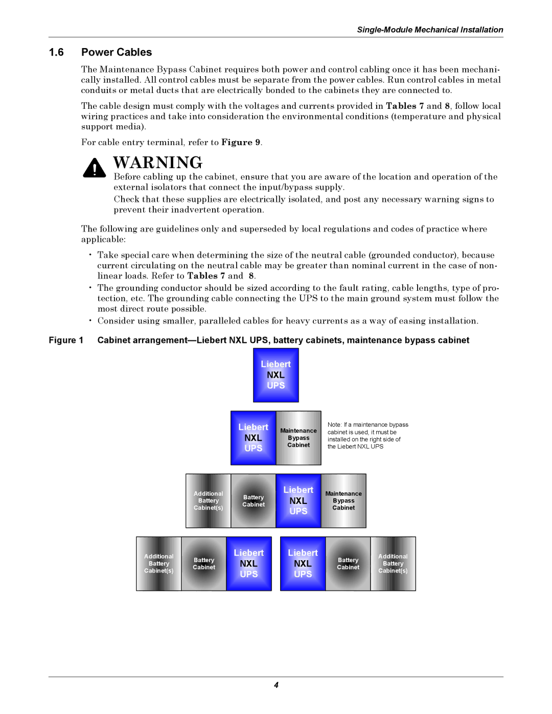
Figure 1 Cabinet arrangement—Liebert NXL UPS, battery cabinets, maintenance bypass cabinet
Liebert
NXL
UPS
Liebert
NXL
UPS
Maintenance
Bypass
Cabinet
Note: If a maintenance bypass cabinet is used, it must be installed on the right side of the Liebert NXL UPS
Additional | Battery | Liebert | Maintenance | |
Battery | NXL | Bypass | ||
Cabinet | ||||
Cabinet(s) |
| UPS | Cabinet | |
|
|
|
Additional
Battery
Cabinet(s)
Battery Cabinet
Liebert
NXL
UPS
Liebert
NXL
UPS
Battery Cabinet
Additional
Battery
Cabinet(s)
4
