Installation Drawings
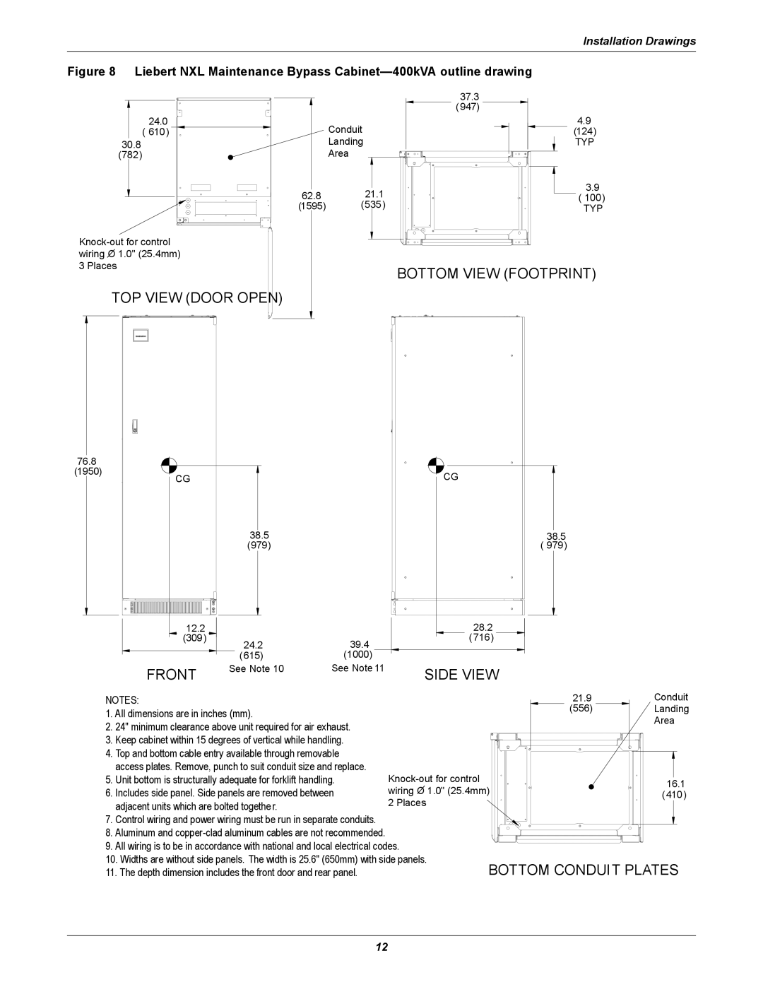
Figure 8 Liebert NXL Maintenance Bypass Cabinet—400kVA outline drawing
|
| 37.3 |
|
| (947) |
24.0 | Conduit | 4.9 |
( 610) | (124) | |
30.8 | Landing | TYP |
(782) | Area |
|
62.8 | 21.1 | 3.9 |
( 100) | ||
(1595) | (535) | TYP |
| |
wiring O 1.0" (25.4mm) |
|
3 Places | BOTTOM VIEW (FOOTPRINT) |
|
TOP VIEW (DOOR OPEN)
76.8 |
|
|
(1950) | CG | CG |
| ||
| 38.5 | 38.5 |
| (979) | ( 979) |
12.2 |
|
| 28.2 |
(309) | 24.2 | 39.4 | ( 716) |
|
|
(615)(1000)
FRONT | See Note 10 | See Note 11 | SIDE VIEW |
|
|
NOTES:
1.All dimensions are in inches (mm).
2.24" minimum clearance above unit required for air exhaust.
3.Keep cabinet within 15 degrees of vertical while handling.
4.Top and bottom cable entry available through removable access plates. Remove, punch to suit conduit size and replace.
5.Unit bottom is structurally adequate for forklift handling.
6. Includes side panel. Side panels are removed between adjacent units which are bolted togethe r.
7.Control wiring and power wiring must be run in separate conduits.
8.Aluminum and
9.All wiring is to be in accordance with national and local electrical codes.
10.Widths are without side panels. The width is 25.6" (650mm) with side panels.
11.The depth dimension includes the front door and rear panel.
21.9Conduit
(556) ![]() Landing
Landing
Area
16.1
(410)
BOTTOM CONDUIT PLATES
12