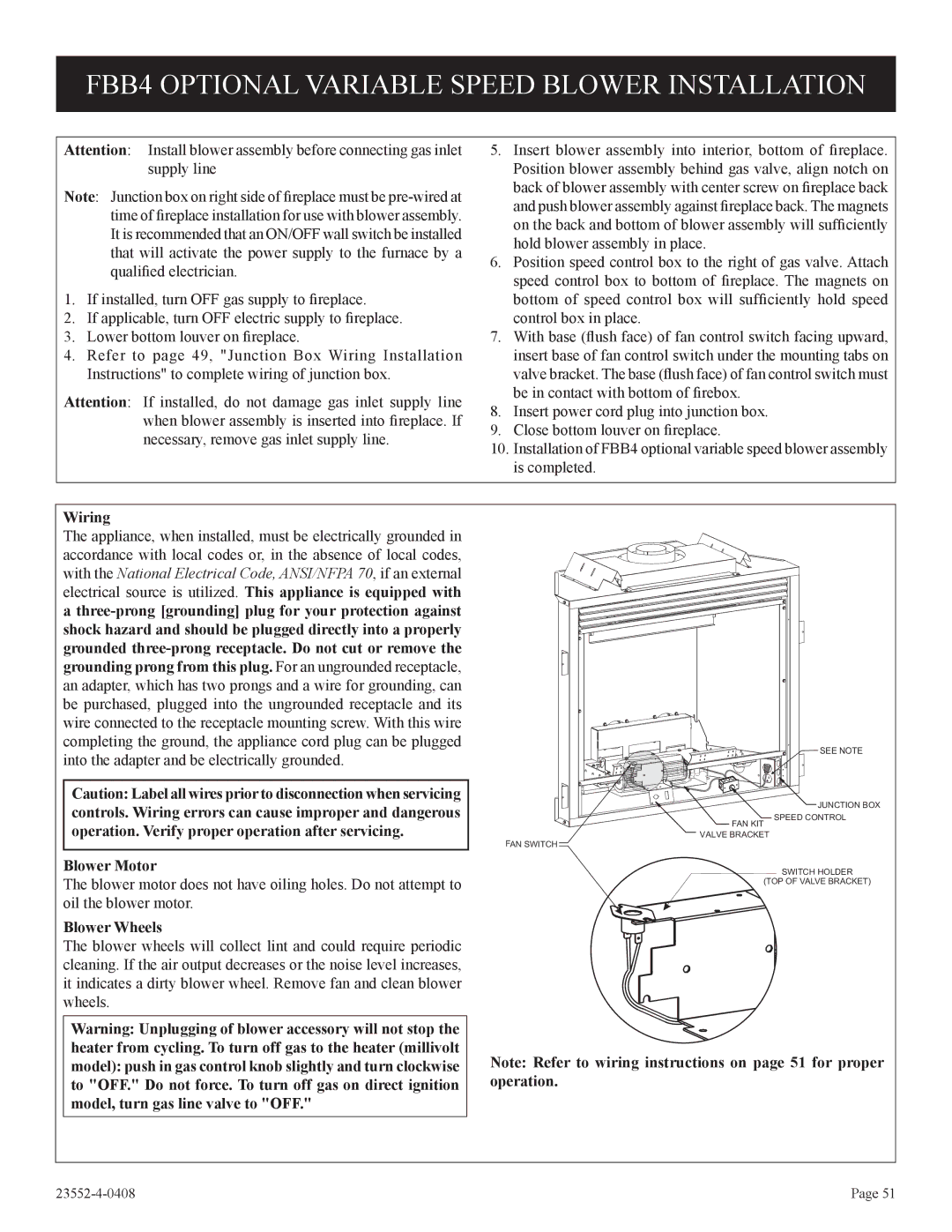
2, 1, DVD32FP3, 3)(N specifications
Empire Comfort Systems has long been a staple in the heating industry, offering innovative solutions for home heating needs. Among their impressive lineup, the Empire Comfort Systems 3)(N,1,2,DVD32FP3 stand-out model highlights a blend of traditional craftsmanship and modern technology. This fireplace insert is designed to provide warmth and an inviting atmosphere to any living space.One of the primary features of the DVD32FP3 is its impressive efficiency. The unit is fueled by natural gas, which not only ensures a dependable heat source but also provides relatively lower operational costs. This model boasts a high efficiency rating, allowing homeowners to enjoy significant savings on utility bills while keeping the environment in mind. Its design allows for efficient heat distribution, ensuring that warmth fills the room without excessive energy consumption.
The Empire 3)(N,1,2,DVD32FP3 also emphasizes user convenience with its innovative controls. It features an adjustable thermostat that allows users to set their desired temperature easily, enhancing comfort levels within the home. A remote control option is also available, adding an extra layer of convenience for adjusting the fireplace settings from anywhere in the room.
Aesthetic appeal is another highlight of this model. With its sleek, contemporary design, the DVD32FP3 can blend seamlessly with various home decors. The unit is equipped with a large viewing window, providing a stunning visual of the flames while also giving a cozy ambiance to the space. The realistic log set enhances the appearance, mimicking the beauty of a traditional wood-burning fireplace without the hassle of wood maintenance.
Safety is of paramount importance with the Empire Comfort Systems 3)(N,1,2,DVD32FP3. It comes with a built-in safety sensor which ensures that the unit operates safely, providing peace of mind to homeowners. Additionally, its zero-clearance design allows for installation in various spaces without needing excessive modifications to existing structures.
Durability is a key characteristic of this fireplace insert, crafted from quality materials that promise longevity in performance. This makes it a reliable choice for home heating needs that can withstand the test of time and usage.
Overall, Empire Comfort Systems 3)(N,1,2,DVD32FP3 stands out for its combination of efficiency, aesthetic appeal, user-friendly features, and safety measures, making it an excellent choice for homeowners looking for comfort and reliability in their heating solutions. Whether you're nestled by the fire on a cold winter night or enhancing your living space, it's a perfect choice for warmth and style.

