DIRECT IGNITION
The Tahoe Direct Vent Zero Clearance Gas
Fireplace Heater
MILLIVOLT
Section
TABLE OF CONTENTS
Page
IMPORTANT SAFETY INFORMATION
NO ODOR DETECTED - ODOR FADE
SAFETY INFORMATION FOR USERS OF LP GAS
That’s your signal to go into immediate action
LP-GASWARNING ODOR
KEEP CLEAR OF ALL OBSTRUCTIONS”
REQUIREMENTS FOR MASSACHUSETTS
Appliance Certification
INTRODUCTION
Instructions to Installer
Qualified Installing Agency
23552-1-0607
SPECIFICATIONS
FIREPLACE DIMENSIONS
performance
Figure Clearances Figure
CLEARANCES
LOCATING FIREPLACE
Mantel Chart Figure
Installing a New Main Gas Cock
GAS SUPPLY
Checking Manifold Pressures
Empire Flexvent Kit DVVK-4F,refer to page
REAR VENT CONVERSION
SPECIAL VENT SYSTEMS
Simpson Duravent GS 4 - 6 ⅝, refer to page
4” Diameter flue 7” Diameter intake vent 1 25 mm
INSTALLATION
Top of Vent 376 mm 125 mm
Combustibles NOT allowed in shaded area
Finishing Figures 12 and
INSTALLATION continued
Flush Mount Mantel Installation Figure
Framing Figure
Vent Runs Figures 14, 15, 16, 17 and
INSTALLATION continued
Flush Wall Installation
Figure Combustible Surround Installation
HORIZONTAL ONLY, STRAIGHT OUT THE BACK
INSTALLATION continued
CORNER INSTALLATION VERTICAL, 90 ELBOW TO
Figure CORNER INSTALLATION HORIZONTAL, 45 ELBOW
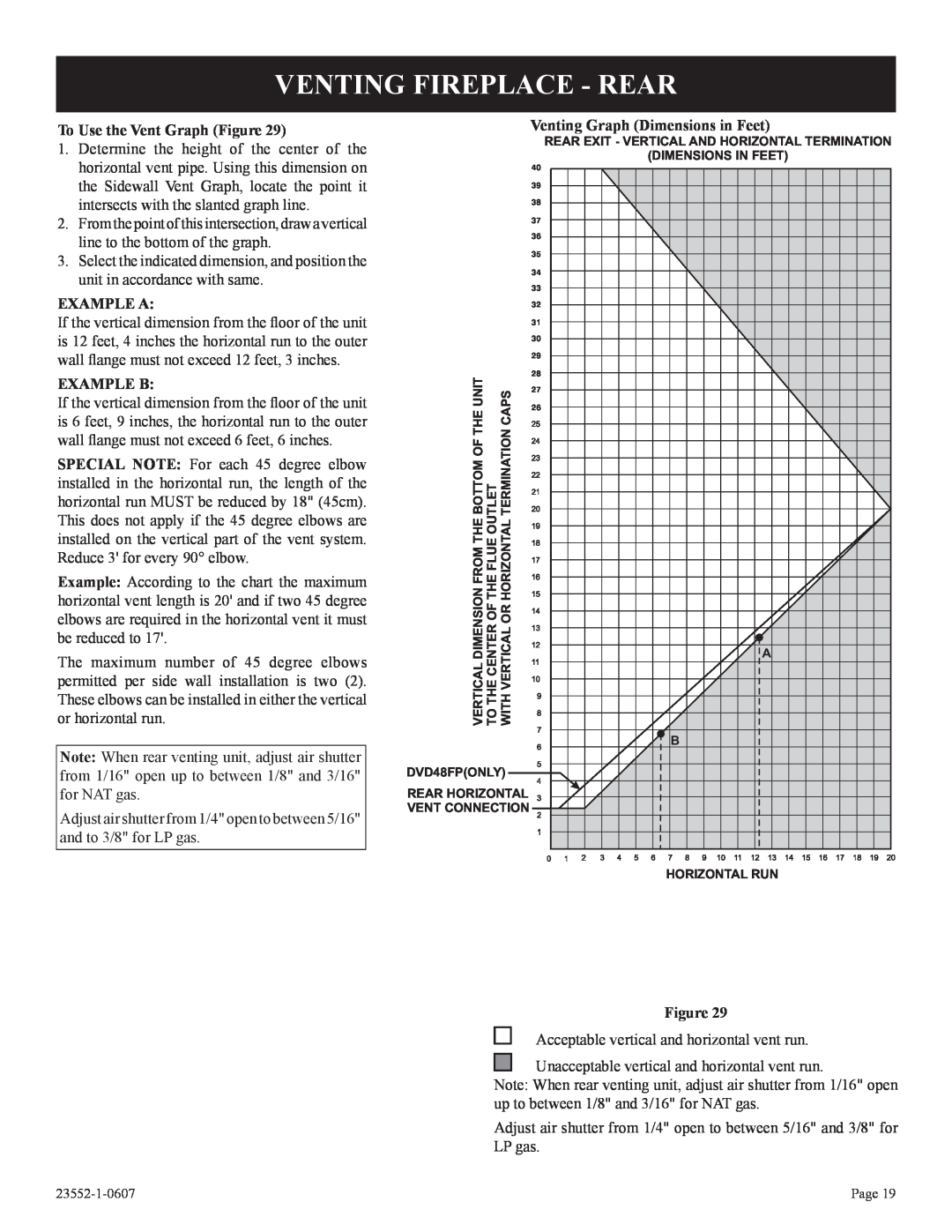
EXAMPLE A
VENTING FIREPLACE - TOP
Venting Graph Dimensions in Feet
To Use the Vent Graph Figure
Below Grade Installation
VENTING FIREPLACE - TOP continued
Cutting the Hole Figures
MAXIMUM HORIZONTAL RUN WITH NO VERTICAL
RISE AND 90 ELBOW
Positioning the Fireplace
23552-1-0607
EXAMPLES - TOP VENT RUN
Figure Figure Figure
Page
EXAMPLE A
VENTING FIREPLACE - REAR
Venting Graph Dimensions in Feet
To Use the Vent Graph Figure
Figure Figure
EXAMPLES - REAR VENT RUN
Vertical Sidewall Installations
TERMINATION CLEARANCES
VENT CLEARANCES
Installing Vent Components Figure
VENT SYSTEM IDENTIFICATION
Installing Support Brackets Figure
FRAMING AND FINISHING
Installing Firestops Figures 38, 39, 40 and
Page
FRAMING AND FINISHING continued
Pages
23552-1-0607
Figure 43a
HORIZONTAL TERMINATION
Figure 43b
Figure Cutting Vent Tubes
DVVK-4REVENT KIT INSTALLATION INSTRUCTIONS
Installing Wall Thimble/Firestop Assembly
Parts Verification
BEYOND EXTERNAL WALL SURFACE OR VINYL SIDING KIT
Figure 3A
EXT. WALL SURFACE OR VINYL SIDING KIT FLUE PIPE
CUT 2 ½”
Follow correct option according to venting method
Connecting Directly to Fireplace
PARTS LIST
Connecting to Rigid Vent System
INSTALLATION
DVVK-4FFLEX VENT INSTRUCTIONS
Determining Minimum Vent Height Above the Roof
VERTICAL TERMINATION
General Maintenance
Installing the Vent System in a Chase
Installation of Vertical Inlet Baffle
VERTICAL TERMINATION continued
Reassembly and Resealing Vent Pipe System
EMBER MATERIAL PLACEMENT ON BURNER
LOG PLACEMENT 5 LOG SET
7 5 6 3 2 1 EMBER MATERIAL PLACEMENT
LOG PLACEMENT 7 LOG SET
Pilot Flame Figure
OPERATING INSTRUCTIONS
750 Millivolt System
Initial Lighting
Installation of Remote Receiver
OPERATING INSTRUCTIONS continued
Wall Switch, FWS-1
Electric 120 volt Operated Remote Control, FREC
Page
STANDING PILOT WIRING DIAGRAM
OPTIONAL THERMOSTAT OPTIONAL WALL SWITCH
23552-1-0607
TO TURN OFF GAS TO FIREPLACE
STANDING PILOT LIGHTING INSTRUCTIONS
FOR YOUR SAFETY READ BEFORE LIGHTING
LIGHTING INSTRUCTIONS
6.Glass soots
STANDING PILOT TROUBLESHOOTING
of problems and the corrective action to be taken
4.Frequent pilot outage problem
OPTIONAL REMOTE CONTROL
DIRECT IGNITION WIRING DIAGRAM
PURGE PROCEDURE
DIRECT IGNITION LIGHTING INSTRUCTIONS
INITIAL START UP GAS LINE PURGE
FOR YOUR SAFETY READ BEFORE LIGHTING
DIRECT IGNITION PROPANE/LP GAS CONVERSION
DIRECT IGNITION TROUBLESHOOTING
Maxitrol Valve Conversion
DIRECT IGNITION PROPANE/LP GAS CONVERSION
Glass Cleaning
MAINTENANCE AND SERVICE
Clean Burner and Control Compartment
Cleaning Procedure
23552-1-0607
PARTS LIST
Page
Page
PARTS VIEW
5 PIECE LOG ASSEMBLY
7 PIECE LOG ASSEMBLY
Blower Motor
FBB4 OPTIONAL VARIABLE SPEED BLOWER INSTALLATION
Blower Wheels
110 VOLT AC
FBB4 OPTIONAL VARIABLE SPEED BLOWER INSTALLATION
JUNCTION BOX FAN BLACK FAN SWITCH WHITE GROUND
BLOWER ASSEMBLY
120V DIRECT IGNITION VALVE MODELS
JUNCTION BOX WIRING INSTALLATION INSTRUCTIONS
OPTIONAL BRICK LINER INSTALLATION INSTRUCTIONS
STANDARD MILLIVOLT VALVE MODELS
DECORATIVE ACCESSORIES
ACCESSORIES
SERVICE NOTES HOW TO ORDER REPAIR PARTS
23552-1-0607
SERVICE NOTES
Empire Comfort Systems, Inc
Page