WIRING
The appliance, when installed, must be electrically grounded in accordance with local codes or, in the absence of local codes, with the National Electrical Code, ANSI/NFPA 70 or Canadian Electri- cal Code, CSA C22.1, if an external electrical source is utilized.
This appliance is equipped with a
CAUTION: Label all wires prior to disconnection when ser- vicing controls. Wiring errors can cause improper and dan- gerous operation. Verify proper operation after servicing.
WARNING: Potential risk of fire, electric shock, and personal injury. Take precautions to reduce such risks.
Note: For testing flame sensor circuit use a
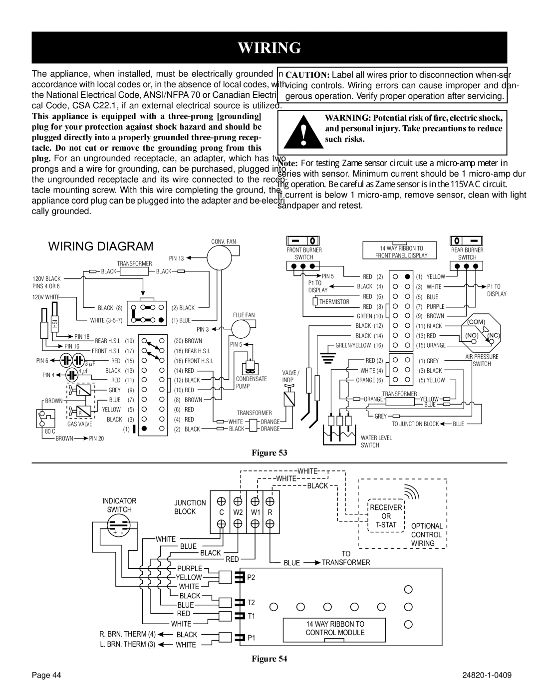
WIRING DIAGRAM
|
|
| TRANSFORMER | |
120V BLACK |
|
| BLACK |
|
|
|
|
| |
PINS 4 OR 6 |
|
|
|
|
120V WHITE |
|
|
|
|
|
|
| BLACK (8) |
|
HSI |
| WHITE |
| |
|
|
|
| |
| PIN 18 | REAR H.S.I. | (19) | |
| PIN 16 | FRONT H.S.I. | (17) | |
|
| |||
PIN 6 | 3 µF | RED | (15) | |
PIN 4 | 4 µF |
| BLACK | (13) |
|
| RED | (11) | |
|
|
| ||
| F |
| GREY | (9) |
BROWN |
|
| BLUE | (7) |
| R |
| YELLOW | (5) |
|
| BLACK | (3) | |
| GAS VALVE | |||
80 C |
| (1) | ||
|
|
| ||
|
| CONV. FAN |
| FRONT BURNER |
|
| 14 WAY RIBBON TO |
| REAR BURNER | |
|
|
|
|
|
|
| ||||
PIN 13 |
|
|
| SWITCH |
|
| FRONT PANEL DISPLAY | SWITCH | ||
BLACK |
|
|
| PIN 5 |
| RED | (2) | (1) | YELLOW |
|
|
|
|
|
|
| |||||
|
|
|
| P1 TO |
| BLACK | (4) | (3) | WHITE | P1 TO |
|
|
|
| DISPLAY |
| |||||
|
|
|
|
| RED | (6) | (5) | BLUE | DISPLAY | |
|
|
|
| THERMISTOR | ||||||
|
|
|
|
| ||||||
(2) BLACK |
|
| RED | (8) | (7) | PURPLE |
| |||
FLUE FAN |
|
|
|
| ||||||
(1) BLUE |
|
|
| GREEN (10) | (9) | BROWN | (COM) | |||
|
|
|
| BLACK (12) | (11) BLACK | |||||
| PIN 3 |
|
|
|
|
| ||||
|
|
|
|
| BLACK (14) | (13) RED | (NO) (NC) | |||
(20) BROWN | PIN 5 |
|
|
| ||||||
|
| GREEN/YELLOW (16) | (15) ORANGE |
| ||||||
(18) REAR H.S.I. |
|
|
| |||||||
|
|
|
|
|
|
|
| AIR PRESSURE | ||
(16) FRONT H.S.I. |
|
|
| RED (2) | (1) GREY | |||||
|
|
| SWITCH | |||||||
(14) RED |
|
| VALVE / |
| WHITE (4) | (3) BLACK | ||||
CONDENSATE |
|
| ||||||||
(12) BLACK | INDP |
| ORANGE (6) | (5) YELLOW |
| |||||
(10) RED | PUMP |
|
|
| ORANGETRANSFORMER YELLOW |
| ||||
|
|
|
|
| ||||||
(8) | BROWN |
|
|
|
|
| ||||
(6) | RED | TRANSFORMER |
|
|
|
|
| BLUE |
| |
|
|
| GREY |
|
|
| ||||
(4) | RED |
|
|
|
|
|
| |||
WHITE | ORANGE |
|
|
| TO JUNCTION BLOCK | BLUE | ||||
|
|
|
| |||||||
(2) | BLACK | BLACK | ORANGE |
|
|
|
|
|
|
|
BROWN |
| PIN 20 |
|
Figure 53
WATER LEVEL SWITCH
|
|
|
| WHITE WHITE |
| |
|
|
|
|
| BLACK |
|
INDICATOR | JUNCTION |
|
|
| RECEIVER |
|
SWITCH | BLOCK | C | W2 | W1 R |
| |
OR |
| |||||
+ - |
|
|
|
| OPTIONAL | |
WHITE |
|
|
|
| CONTROL | |
|
|
|
|
| WIRING | |
| BLUE BLACK |
|
| TO | ||
| RED | BLUE |
| |||
| PURPLE |
|
| TRANSFORMER |
| |
|
|
| P2 |
|
| |
| YELLOW |
|
|
|
| |
| WHITE |
|
|
|
|
|
| BLACK |
|
| T2 |
|
|
| BLUE |
|
|
|
| |
| RED |
|
| T1 | 14 WAY RIBBON TO |
|
| WHITE |
|
|
|
| |
R. BRN. THERM (4) | BLACK |
|
| P1 | CONTROL MODULE |
|
L. BRN. THERM (3) | WHITE |
|
|
|
| |
|
|
|
|
| ||
Figure 54
Page 44 |