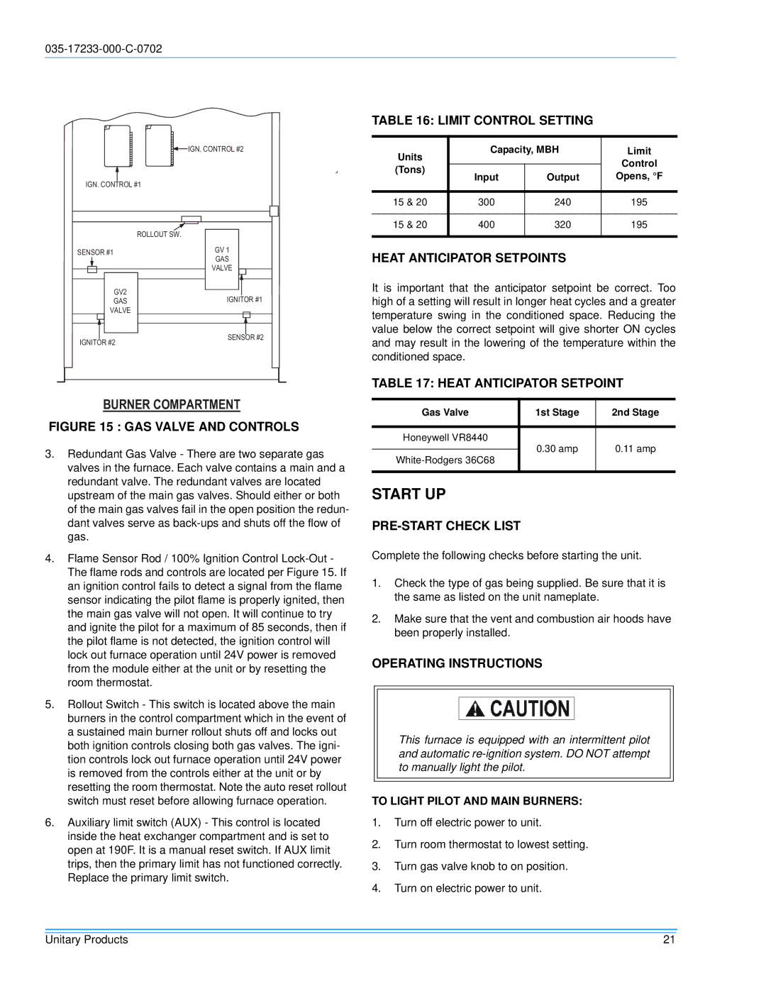
DHG180, DHG240 specifications
Energy Tech Laboratories has made significant strides in the realm of energy efficiency and renewable technologies with the introduction of their innovative models, the DHG240 and DHG180. These advanced devices are designed to optimize energy consumption, minimize environmental impact, and enhance overall energy management.The DHG240 model stands out with its high-capacity performance, delivering a robust output of 240 kW. This unit is ideal for large facilities and industrial applications, where energy demands are high. One of its main features is its advanced algorithm for energy distribution, which allows for optimal load balancing across various operational units. This ensures that energy is used efficiently, reducing waste and lowering operational costs.
Similarly, the DHG180 is designed for medium-sized operations, providing an output of 180 kW. It offers an effective solution for businesses seeking to improve energy efficiency without the excessive overhead costs typically associated with larger systems. The DHG180 incorporates state-of-the-art monitoring systems that provide real-time data on energy consumption, allowing operators to make informed decisions and adjust settings as needed.
Both models integrate cutting-edge technologies such as smart grid capabilities and renewable energy sources. They are equipped to handle integration with solar panels and wind turbines, enabling facilities to harness clean energy and reduce reliance on fossil fuels. This feature not only contributes to sustainability goals but also provides a buffer against fluctuating energy prices.
The design of both the DHG240 and DHG180 prioritizes durability and reliability. They are constructed from high-quality materials that withstand harsh operational conditions, ensuring a long lifespan and reduced maintenance costs. Furthermore, these systems are compliant with various energy efficiency standards, making them a responsible choice for environmentally conscious businesses.
User-friendliness is another hallmark of these devices. An intuitive interface allows operators to easily monitor and control energy usage, while remote access compatibility enables management from off-site locations. This flexibility is crucial in today’s fast-paced business environment.
In conclusion, Energy Tech Laboratories’ DHG240 and DHG180 models represent the forefront of energy technology. By delivering high performance, integrating renewable solutions, and prioritizing ease of use, these units empower businesses to achieve their energy efficiency goals while promoting sustainability. Whether for large industries or medium-sized enterprises, these systems are engineered to meet the dynamic needs of modern energy management.

