035-17233-000-C-0702

LOCATION

Use the following guidelines to select a suitable location for these units.

1.Unit is designed for outdoor installation only.

2.Condenser coils must have an unlimited supply of air. Where a choice of location is possible, position the unit on either north or east side of building.

Excessive exposure of this furnace to contami- nated combustion air may result equipment dam- age or personal injury. Typical contaminates include: permanent wave solutions, chlorinated waxes and cleaners, chlorine based swimming pool chemicals, water softening chemicals, carbon tetrachloride, Halogen type refrigerants, cleaning solvents (e.g. perchloroethylene), printing inks, paint removers, varnishes, hydrochloric acid, cements and glues, antistatic fabric softeners for clothes dryers, masonry acid washing materials.

3.For ground level installation, use a level concrete slab with a minimum thickness of 4 inches. The length and width should be at least 6 inches greater than the unit base rails. Do not tie slab to the building foundation.

4.Roof structures must be able to support the weight of the unit and its options and/or accessories. Unit must be installed on a solid level roof curb or appropriate angle iron frame.

Length of the forks must be a minimum of 90”.

An adhesive backed label is provided over the out- side of the combustion air inlet opening to prevent moisture from entering the unit which could cause damage to electrical components. Allow this clo- sure label to remain in place until the combustion air hood is to be installed (refer to Figure 7).

If a unit is to be installed on a roof curb or special frame other than a YORK roof curb, gasketing must be applied to all surfaces that come in con- tact with the unit underside.

5.Maintain level tolerance to 1/2" maximum across the entire length or width of the unit.

RIGGING AND HANDLING

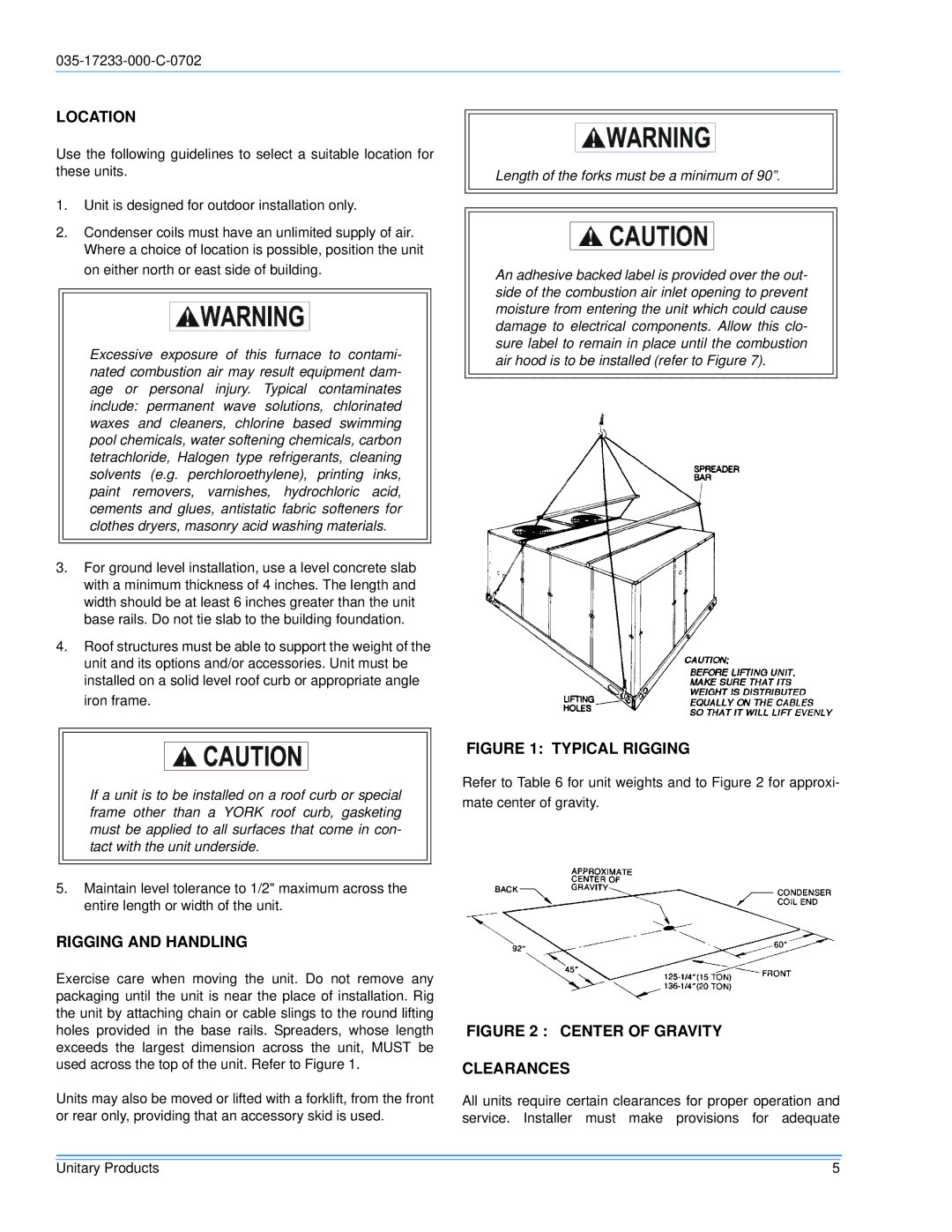
Exercise care when moving the unit. Do not remove any packaging until the unit is near the place of installation. Rig the unit by attaching chain or cable slings to the round lifting holes provided in the base rails. Spreaders, whose length exceeds the largest dimension across the unit, MUST be used across the top of the unit. Refer to Figure 1.

Units may also be moved or lifted with a forklift, from the front or rear only, providing that an accessory skid is used.

FIGURE 1: TYPICAL RIGGING

Refer to Table 6 for unit weights and to Figure 2 for approxi-

mate center of gravity.

FIGURE 2 : CENTER OF GRAVITY

CLEARANCES

All units require certain clearances for proper operation and service. Installer must make provisions for adequate

Unitary Products

5

Page 5
Image 5
Energy Tech Laboratories DHG180, DHG240 installation instructions Location, Rigging and Handling

DHG180, DHG240 specifications

Energy Tech Laboratories has made significant strides in the realm of energy efficiency and renewable technologies with the introduction of their innovative models, the DHG240 and DHG180. These advanced devices are designed to optimize energy consumption, minimize environmental impact, and enhance overall energy management.

The DHG240 model stands out with its high-capacity performance, delivering a robust output of 240 kW. This unit is ideal for large facilities and industrial applications, where energy demands are high. One of its main features is its advanced algorithm for energy distribution, which allows for optimal load balancing across various operational units. This ensures that energy is used efficiently, reducing waste and lowering operational costs.

Similarly, the DHG180 is designed for medium-sized operations, providing an output of 180 kW. It offers an effective solution for businesses seeking to improve energy efficiency without the excessive overhead costs typically associated with larger systems. The DHG180 incorporates state-of-the-art monitoring systems that provide real-time data on energy consumption, allowing operators to make informed decisions and adjust settings as needed.

Both models integrate cutting-edge technologies such as smart grid capabilities and renewable energy sources. They are equipped to handle integration with solar panels and wind turbines, enabling facilities to harness clean energy and reduce reliance on fossil fuels. This feature not only contributes to sustainability goals but also provides a buffer against fluctuating energy prices.

The design of both the DHG240 and DHG180 prioritizes durability and reliability. They are constructed from high-quality materials that withstand harsh operational conditions, ensuring a long lifespan and reduced maintenance costs. Furthermore, these systems are compliant with various energy efficiency standards, making them a responsible choice for environmentally conscious businesses.

User-friendliness is another hallmark of these devices. An intuitive interface allows operators to easily monitor and control energy usage, while remote access compatibility enables management from off-site locations. This flexibility is crucial in today’s fast-paced business environment.

In conclusion, Energy Tech Laboratories’ DHG240 and DHG180 models represent the forefront of energy technology. By delivering high performance, integrating renewable solutions, and prioritizing ease of use, these units empower businesses to achieve their energy efficiency goals while promoting sustainability. Whether for large industries or medium-sized enterprises, these systems are engineered to meet the dynamic needs of modern energy management.