Energy Tech Laboratories DHG240 POST-START Check List GAS, Manifold GAS Pressure Adjustment

Models: DHG180 DHG240

1 28
Download 28 pages 15.66 Kb
Page 22
Image 22

035-17233-000-C-0702

5.Set room thermostat to desired temperature.(If thermo- stat set temperature is above room temperature, pilot burner ignition will occur and, after an interval to prove pilot flame, main burners will ignite).

TO SHUT DOWN:

1.Turn off electric power to unit.

2.Depress knob of gas valve while turning to off position.

POST-START CHECK LIST (GAS)

After the entire control circuit has been energized and the heating section is operating, make the following checks:

1.Check for gas leaks in the unit piping as well as the sup- ply piping.

2.Check for correct manifold gas pressures. See Checking Gas Input.

3.Check the supply gas pressure. It must be within the lim- its shown on rating nameplate. Supply pressure should be checked with all gas appliances in the building at full fire. At no time should the standby gas line pressure exceed 13", nor the operating pressure drop below 5.0" for natural gas units. If gas pressure is outside these lim- its, contact the local gas utility for corrective action.

MANIFOLD GAS PRESSURE ADJUSTMENT

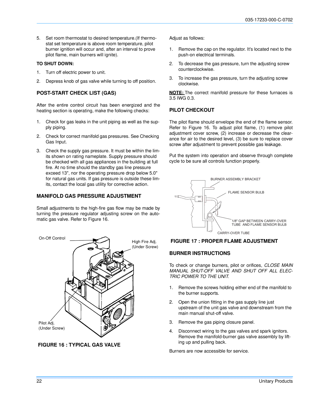
Small adjustments to the high-fire gas flow may be made by turning the pressure regulator adjusting screw on the auto- matic gas valve. Refer to Figure 16.

On-Off Control

High Fire Adj.

(Under Screw)

Pilot Adj.

(Under Screw)

FIGURE 16 : TYPICAL GAS VALVE

Adjust as follows:

1.Remove the cap on the regulator. It's located next to the push-on electrical terminals.

2.To decrease the gas pressure, turn the adjusting screw counterclockwise.

3.To increase the gas pressure, turn the adjusting screw clockwise.

NOTE: The correct manifold pressure for these furnaces is 3.5 IWG 0.3.

PILOT CHECKOUT

The pilot flame should envelope the end of the flame sensor. Refer to Figure 16. To adjust pilot flame, (1) remove pilot adjustment cover screw, (2) increase or decrease the clear- ance for air to the desired level, (3) be sure to replace cover screw after adjustment to prevent possible gas leakage.

Put the system into operation and observe through complete cycle to be sure all controls function properly.

BURNERASSEMBLYBRACKET

FLAMESENSORBULB

1/8"GAPBETWEENCARRY-OVER TUBE ANDFLAMESENSORBULB

CARRY-OVERTUBE

FIGURE 17 : PROPER FLAME ADJUSTMENT

BURNER INSTRUCTIONS

To check or change burners, pilot or orifices, CLOSE MAIN MANUAL SHUT-OFF VALVE AND SHUT OFF ALL ELEC- TRIC POWER TO THE UNIT.

1.Remove the screws holding either end of the manifold to the burner supports.

2.Open the union fitting in the gas supply line just upstream of the unit gas valve and downstream from the main manual shut-off valve.

3.Remove the gas piping closure panel.

4.Disconnect wiring to the gas valves and spark ignitors. Remove the manifold-burner gas valve assembly by lift- ing up and pulling back.

Burners are now accessible for service.

22

Unitary Products

Page 22
Image 22
Energy Tech Laboratories DHG240 POST-START Check List GAS, Manifold GAS Pressure Adjustment, Pilot Checkout, To Shut Down

DHG180, DHG240 specifications

Energy Tech Laboratories has made significant strides in the realm of energy efficiency and renewable technologies with the introduction of their innovative models, the DHG240 and DHG180. These advanced devices are designed to optimize energy consumption, minimize environmental impact, and enhance overall energy management.

The DHG240 model stands out with its high-capacity performance, delivering a robust output of 240 kW. This unit is ideal for large facilities and industrial applications, where energy demands are high. One of its main features is its advanced algorithm for energy distribution, which allows for optimal load balancing across various operational units. This ensures that energy is used efficiently, reducing waste and lowering operational costs.

Similarly, the DHG180 is designed for medium-sized operations, providing an output of 180 kW. It offers an effective solution for businesses seeking to improve energy efficiency without the excessive overhead costs typically associated with larger systems. The DHG180 incorporates state-of-the-art monitoring systems that provide real-time data on energy consumption, allowing operators to make informed decisions and adjust settings as needed.

Both models integrate cutting-edge technologies such as smart grid capabilities and renewable energy sources. They are equipped to handle integration with solar panels and wind turbines, enabling facilities to harness clean energy and reduce reliance on fossil fuels. This feature not only contributes to sustainability goals but also provides a buffer against fluctuating energy prices.

The design of both the DHG240 and DHG180 prioritizes durability and reliability. They are constructed from high-quality materials that withstand harsh operational conditions, ensuring a long lifespan and reduced maintenance costs. Furthermore, these systems are compliant with various energy efficiency standards, making them a responsible choice for environmentally conscious businesses.

User-friendliness is another hallmark of these devices. An intuitive interface allows operators to easily monitor and control energy usage, while remote access compatibility enables management from off-site locations. This flexibility is crucial in today’s fast-paced business environment.

In conclusion, Energy Tech Laboratories’ DHG240 and DHG180 models represent the forefront of energy technology. By delivering high performance, integrating renewable solutions, and prioritizing ease of use, these units empower businesses to achieve their energy efficiency goals while promoting sustainability. Whether for large industries or medium-sized enterprises, these systems are engineered to meet the dynamic needs of modern energy management.