Using LANVIEW
Using LANVIEW
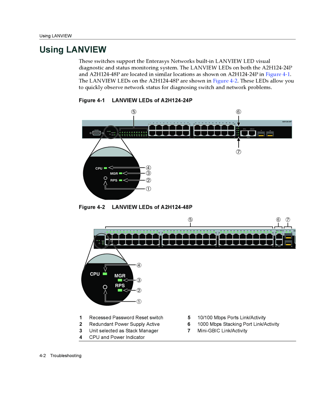
These switches support the Enterasys Networks built‐in LANVIEW LED visual diagnostic and status monitoring system. The LANVIEW LEDs on both the A2H124‐24P and A2H124‐48P are located in similar locations as shown on A2H124‐24P in Figure 4‐1. The LANVIEW LEDs on the A2H124‐48P are shown in Figure 4‐2. These LEDs allow you to quickly observe network status for diagnosing switch and network problems.
Figure 4-1 LANVIEW LEDs of A2H124-24P
ÄÅ
|
|
|
|
|
|
|
|
|
|
|
|
| 1 | 2 | 3 | 4 | 5 | 6 | 7 | 8 | 9 | 10 | 11 | 12 |
| 13 13 | 14 | 15 | 16 | 17 | 18 | 19 | 20 | 21 | 22 | 23 | 24 23 |
|
| |
|
|
|
|
|
|
|
|
|
|
|
| 1 | 11 |
|
|
| ||||||||||||||||||||||||
|
|
|
|
|
|
|
|
|
|
|
|
|
|
|
|
|
|
|
|
|
|
|
|
|
|
|
|
|
|
|
|
|
|
|
|
| 25 | 25/Up | 26/Down |
|
Console |
|
|
|
|
|
|
|
|
|
|
|
|
|
|
|
|
|
|
|
|
|
|
|
|
|
|
|
|
|
|
|
|
|
|
|
| 26 |
| 27 | 28 |
CPU | 1 | 3 | 5 | 7 | 9 | 11 | 13 | 15 | 17 | 19 | 21 | 23 |
|
|
|
|
|
|
|
|
|
|
|
|
|
|
|
|
|
|
|
|
|
|
|
|
|
|
|
|
| MGR |
|
|
|
|
|
|
|
|
|
|
|
|
|
|
|
|
|
|
|
|
|
|
|
|
|
|
|
|
|
|
|
|
|
|
| 27 |
|
|
|
| RPS | 4 | 6 | 8 | 10 | 12 | 14 | 16 | 18 | 20 | 22 | 24 |
|
|
|
|
|
|
|
|
|
|
|
|
|
|
|
|
|
|
|
|
|
|
|
| 28 |
|
|
|
| 2 |
|
|
|
|
|
|
|
|
|
|
|
|
|
|
|
|
|
|
|
|
|
|
|
|
|
|
|
| |||||||||||
|
|
|
|
|
|
|
|
|
|
|
| 2 |
|
|
|
|
|
|
|
|
|
|
|
| 12 | 14 |
|
|
|
|
|
|
|
|
|
| 24 |
| Stack |
|
CPU 

MGR 

RPS 

Æ
Ã
Â
Á
À
Figure |
|
|
|
|
|
| ||
|
| Ä |
|
|
| Å Æ |
|
|
1 | 2 3 4 5 6 7 8 9 10 11 12 13 14 15 16 | 17 18 19 20 21 22 23 24 25 26 27 28 29 30 31 32 |
| 33 34 35 36 37 38 39 40 41 42 43 44 45 46 47 48 |
| 49/Up 50/Down 51 52 |
| A2 |
1 | 15 | 17 | 31 | 33 | 47 | 49 | 51 |
|
CPU MGR |
|
|
|
|
|
|
|
|
RPS |
|
|
|
|
|
|
|
|
2 | 16 | 18 | 32 | 34 | 48 | 50 Stack | 52 | C |
CPU ![]() MGR
MGR
RPS
Ã
Â
Á
À
1 | Recessed Password Reset switch | 5 | 10/100 Mbps Ports Link/Activity |
2 | Redundant Power Supply Active | 6 | 1000 Mbps Stacking Port Link/Activity |
3 | Unit selected as Stack Manager | 7 |
|
4CPU and Power Indicator
