Installation

CHIMNEY INSTALLATION THROUGH WALL:

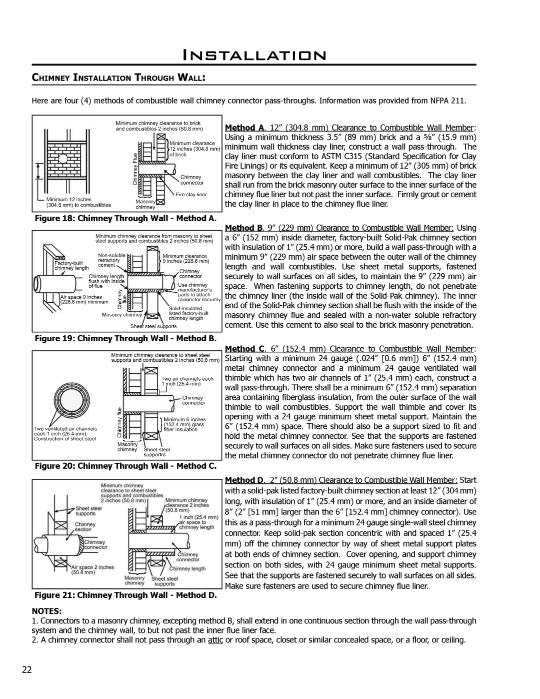
Here are four (4) methods of combustible wall chimney connector pass-throughs. Information was provided from NFPA 211.

Figure 18: Chimney Through Wall - Method A.

Figure 19: Chimney Through Wall - Method B.

Figure 20: Chimney Through Wall - Method C.

Method A. 12” (304.8 mm) Clearance to Combustible Wall Member: Using a minimum thickness 3.5” (89 mm) brick and a 5⁄8” (15.9 mm) minimum wall thickness clay liner, construct a wall pass-through. The clay liner must conform to ASTM C315 (Standard Specification for Clay Fire Linings) or its equivalent. Keep a minimum of 12” (305 mm) of brick masonry between the clay liner and wall combustibles. The clay liner shall run from the brick masonry outer surface to the inner surface of the chimney flue liner but not past the inner surface. Firmly grout or cement the clay liner in place to the chimney flue liner.

Method B. 9” (229 mm) Clearance to Combustible Wall Member: Using a 6” (152 mm) inside diameter, factory-built Solid-Pak chimney section with insulation of 1” (25.4 mm) or more, build a wall pass-through with a minimum 9” (229 mm) air space between the outer wall of the chimney length and wall combustibles. Use sheet metal supports, fastened securely to wall surfaces on all sides, to maintain the 9” (229 mm) air space. When fastening supports to chimney length, do not penetrate the chimney liner (the inside wall of the Solid-Pak chimney). The inner end of the Solid-Pak chimney section shall be flush with the inside of the masonry chimney flue and sealed with a non-water soluble refractory cement. Use this cement to also seal to the brick masonry penetration.

Method C. 6” (152.4 mm) Clearance to Combustible Wall Member: Starting with a minimum 24 gauge (.024” [0.6 mm]) 6” (152.4 mm) metal chimney connector and a minimum 24 gauge ventilated wall thimble which has two air channels of 1” (25.4 mm) each, construct a wall pass-through. There shall be a minimum 6” (152.4 mm) separation area containing fiberglass insulation, from the outer surface of the wall thimble to wall combustibles. Support the wall thimble and cover its opening with a 24 gauge minimum sheet metal support. Maintain the 6” (152.4 mm) space. There should also be a support sized to fit and hold the metal chimney connector. See that the supports are fastened securely to wall surfaces on all sides. Make sure fasteners used to secure the metal chimney connector do not penetrate chimney flue liner.

Method D. 2” (50.8 mm) Clearance to Combustible Wall Member: Start

with a solid-pak listed factory-built chimney section at least 12” (304 mm) long, with insulation of 1” (25.4 mm) or more, and an inside diameter of 8” (2” [51 mm] larger than the 6” [152.4 mm] chimney connector). Use this as a pass-through for a minimum 24 gauge single-wall steel chimney connector. Keep solid-pak section concentric with and spaced 1” (25.4

mm)off the chimney connector by way of sheet metal support plates at both ends of chimney section. Cover opening, and support chimney section on both sides, with 24 gauge minimum sheet metal supports. See that the supports are fastened securely to wall surfaces on all sides. Make sure fasteners are used to secure chimney flue liner.

Figure 21: Chimney Through Wall - Method D.

NOTES:

1.Connectors to a masonry chimney, excepting method B, shall extend in one continuous section through the wall pass-through system and the chimney wall, to but not past the inner flue liner face.

2.A chimney connector shall not pass through an attic or roof space, closet or similar concealed space, or a floor, or ceiling.

22

Page 22
Image 22
Enviro 1700, 1200 owner manual Chimney Through Wall Method a

1700, 1200 specifications

The Enviro 1200 and 1700 are innovative solutions in the world of air treatment and environmental control. Designed to cater to industrial and commercial needs, these models are pivotal in enhancing air quality and promoting energy efficiency.

One of the main features of the Enviro 1200 is its advanced filtration system. It utilizes a multi-stage filtration process that includes pre-filters, HEPA filters, and activated carbon filters. This combination ensures the capture of particulate matter, volatile organic compounds (VOCs), and other airborne contaminants, providing cleaner and healthier air. The Enviro 1700, while similar in filtration capabilities, boasts a larger capacity, making it suitable for bigger spaces or industrial applications.

Both models incorporate smart sensor technologies that monitor air quality in real-time. These sensors provide data on pollutant levels, allowing for dynamic adjustments to the filtration strength. This not only optimizes performance but also reduces energy consumption, making the Enviro series both eco-friendly and cost-effective. The adaptive response of these systems ensures that users always breathe cleaner air without unnecessary energy expenditure.

Another defining characteristic of the Enviro 1200 and 1700 is their user-friendly interface. These units are designed with digital controls, allowing for easy programming and monitoring. Users can set specific operating schedules and track air quality trends over time. Additionally, both models come equipped with WiFi connectivity, enabling remote control via a smartphone app. This feature allows users to adjust settings or receive alerts about air quality levels from anywhere.

In terms of durability, both the Enviro 1200 and 1700 are constructed with high-quality materials that ensure long-lasting performance. They are designed to operate quietly, reducing the noise levels often associated with air treatment systems. This makes them suitable for a range of environments, from offices and homes to industrial settings.

In summary, the Enviro 1200 and 1700 stand out in the air treatment market due to their state-of-the-art filtration, smart technology integration, and user-centric design. These features, combined with their robust build quality, make them a reliable choice for anyone looking to improve air quality while maintaining energy efficiency.