Manuals
/
Enviro
/
Household Appliance
/
Indoor Fireplace
Enviro
DV50DX Initial Installation, Qualified Installers Only, Possible Vent Configurations
Models:
DV50DX
1
18
36
36
Download
36 pages
17.96 Kb
15
16
17
18
19
20
21
22
Troubleshooting
Specification
Install
Parts list
Parts Diagram
Warranty
Maintenance
Log Set Assembly
Cleaning Decorative Surfaces
Safety Precautions
Page 18
Image 18
Page 17
Page 19
Page 18
Image 18
Page 17
Page 19
Contents
Open windows/extinguish any open flame
WHAT TO DO IF YOU SMELL GAS
DV50DX
Do not try to light any appliance
Safety Precautions
FOR YOUR SAFETY
GENERAL
Table of Contents
Codes And Approvals
VENTED GAS FIREPLACE HEATER DV50DX NG/LPG
This ENVIRO DV50DX Fireplace
Specifications
INSTALLATION OPTIONS
LIGHTING INSTRUCTIONS
Operating Instructions
FOR YOUR SAFETY READ BEFORE
PILOT LIGHTING INSTRUCTIONS
NEVER USE AN OPEN FLAME FOR LEAK TESTING
Operating Instructions
Operating Instructions
TO TURN GAS FIREPLACE OFF
CLEANING THE GLASS
Maintenance And Service
ROUTINE MAINTENANCE
CLEANING THE FIREBOX
GLASS DOOR REMOVAL
Maintenance And Service
CLEANING DECORATIVE SURFACES
Figure 8. Glass Removal Handle
Step
Maintenance And Service
Step
Step
Initial Installation
QUALIFIED INSTALLERS ONLY
CORNER INSTALLATION
Initial Installation
QUALIFIED INSTALLERS ONLY
Figure 11. Dimensions for a corner installation
FIREPLACE SURROUND
Initial Installation
QUALIFIED INSTALLERS ONLY
Figure 14. Raised Fireplace with Raised Hearth
Initial Installation
QUALIFIED INSTALLERS ONLY
Top of unit to horizontal framing 12 5/16” 313 mm
Initial Installation
QUALIFIED INSTALLERS ONLY
Initial Installation
QUALIFIED INSTALLERS ONLY
mm of clearance are necessary. See Figure
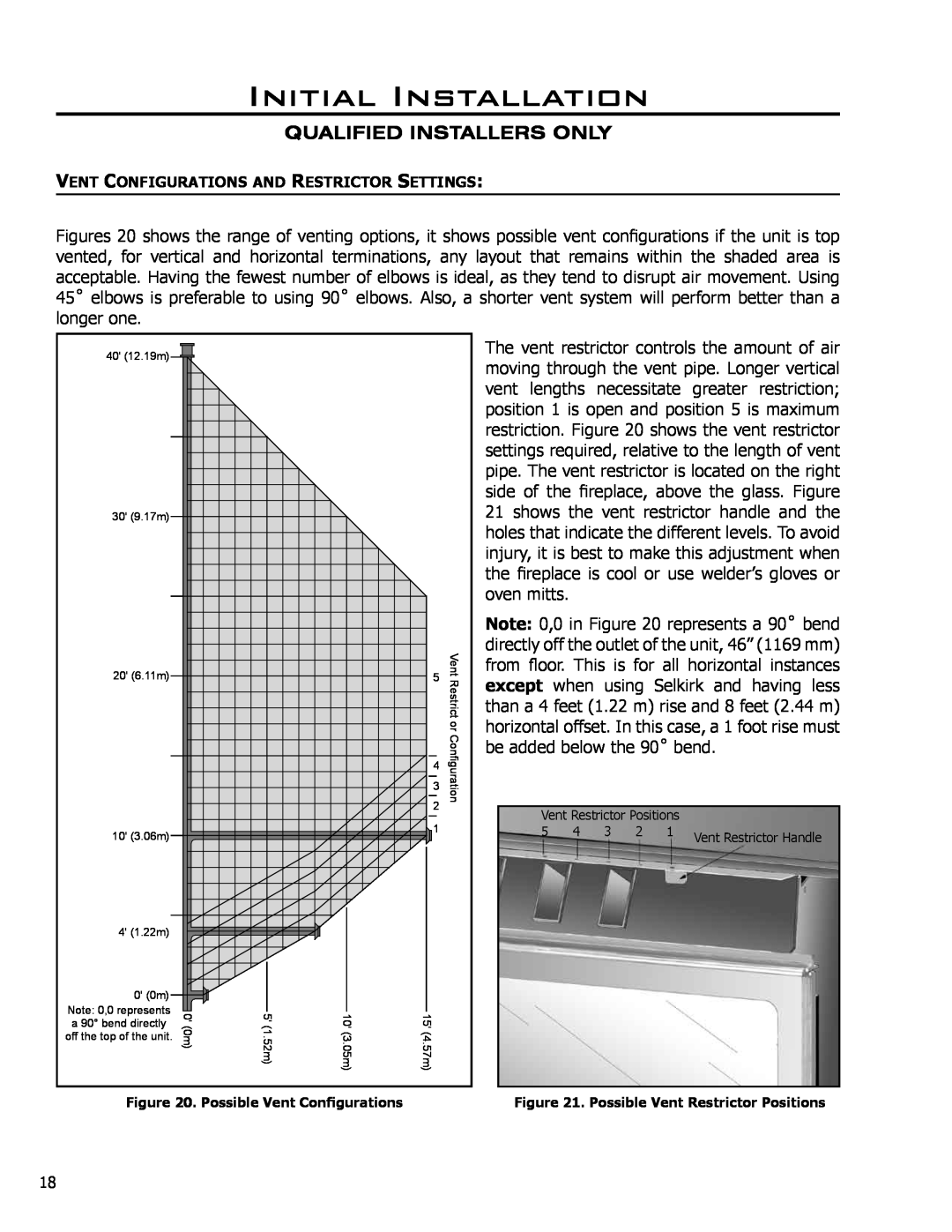
VENT CONFIGURATIONS AND RESTRICTOR SETTINGS
Initial Installation
QUALIFIED INSTALLERS ONLY
Figure 20. Possible Vent Configurations
Initial Installation
QUALIFIED INSTALLERS ONLY
the possibility of a fire
Initial Installation
QUALIFIED INSTALLERS ONLY
Step 4. Assemble
Initial Installation
QUALIFIED INSTALLERS ONLY
STEP 10. Twist-lockthe vent cap
Figure 26 Multi-StoryVent Pipe Installation
Initial Installation
QUALIFIED INSTALLERS ONLY
Figure 25 Use of Wall Straps
DUCTING
Initial Installation
QUALIFIED INSTALLERS ONLY
Figure 27. Heat Dumping Options
Initial Installation
QUALIFIED INSTALLERS ONLY
ELECTRICAL REQUIREMENTS
GAS LINE CONNECTION
NEVER USE AN OPEN FLAME FOR LEAK TESTING
Initial Installation
TO TEST VALVE PRESSURES
Secondary Installation
WARNING DO NOT INSTALL LINER IF UNIT IS HOT
Important installation notes
Figure 35. First Stage Log Set Installation
Secondary Installation
LOG SET ASSEMBLY
Figure 36. Second Stage Log Set Installation
Figure 39. Fifth Stage Log Set Installation
Secondary Installation
Figure 38. Fourth Stage Log Set Installation
Figure 40. Final Log Set Arrangement
Secondary Installation
Figure 42 The DV50DX burning with a good flame
Secondary Installation
screws and the control panel
Solution
Troubleshooting
Problem
Possible Cause
Description
Parts List - Components
Reference
Part
Parts Diagram
DV50DX - Components
November
Parts List- Options
Options
Part Number
Warranty
TO THE DEALER
TO THE DISTRIBUTOR
Installation Data Sheet
Top
Page
Image
Contents