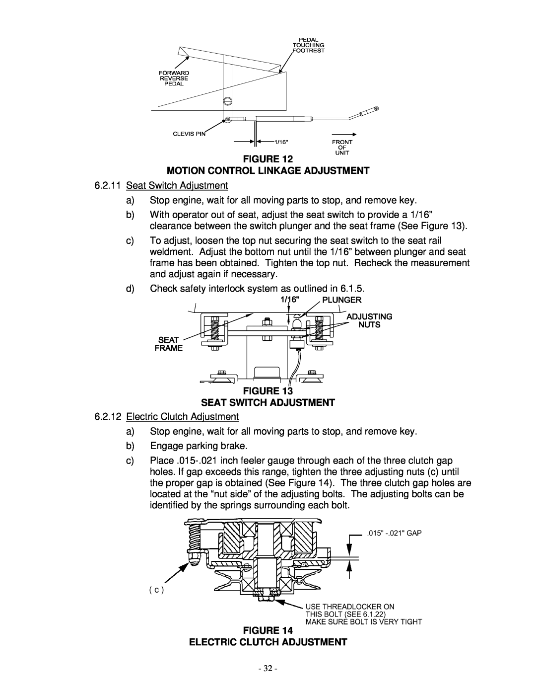
FIGURE 12
MOTION CONTROL LINKAGE ADJUSTMENT
6.2.11Seat Switch Adjustment
a)Stop engine, wait for all moving parts to stop, and remove key.
b)With operator out of seat, adjust the seat switch to provide a 1/16” clearance between the switch plunger and the seat frame (See Figure 13).
c)To adjust, loosen the top nut securing the seat switch to the seat rail weldment. Adjust the bottom nut until the 1/16” between plunger and seat frame has been obtained. Tighten the top nut. Recheck the measurement and adjust again if necessary.
d)Check safety interlock system as outlined in 6.1.5.
FIGURE 13
SEAT SWITCH ADJUSTMENT
6.2.12Electric Clutch Adjustment
a)Stop engine, wait for all moving parts to stop, and remove key.
b)Engage parking brake.
c)
( c )
FIGURE 14
ELECTRIC CLUTCH ADJUSTMENT
- 32 -