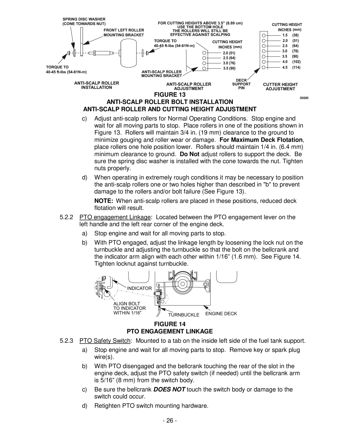
FIGURE 13
c)Adjust
d)When operating in extremely rough conditions it may be necessary to position the
NOTE: When
5.2.2PTO engagement Linkage: Located between the PTO engagement lever on the left handle and the left rear corner of the engine deck.
a)Stop engine and wait for all moving parts to stop.
b)With PTO engaged, adjust the linkage length by loosening the lock nut on the turnbuckle and adjusting the turnbuckle so that the bolt on the bellcrank and the indicator arm align with each other within 1/16” (1.6 mm). See Figure 14. Tighten locknut against turnbuckle.
FIGURE 14
PTO ENGAGEMENT LINKAGE
5.2.3PTO Safety Switch: Mounted to a tab on the inside left side of the fuel tank support.
a)Stop engine and wait for all moving parts to stop. Remove key or spark plug wire(s).
b)With PTO disengaged and the bellcrank touching the rear of the slot in the engine deck, adjust the PTO safety switch (if needed) until the bellcrank arm is 5/16” (8 mm) from the switch body.
c)Be sure the bellcrank DOES NOT touch the switch body or damage to the switch could occur.
d)Retighten PTO switch mounting hardware.
-26 -