Appendix, cont’d
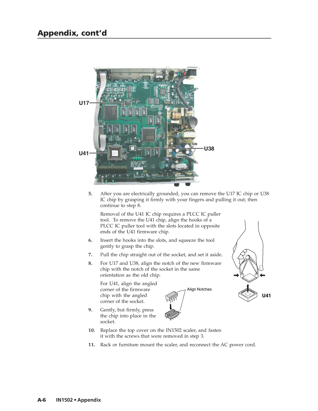
U17
U38
U41
5.After you are electrically grounded, you can remove the U17 IC chip or U38 IC chip by grasping it firmly with your fingers and pulling it out; then continue to step 8.
Removal of the U41 IC chip requires a PLCC IC puller tool. To remove the U41 chip, align the hooks of a PLCC IC puller tool with the slots located in opposite ends of the U41 firmware chip.
6.Insert the hooks into the slots, and squeeze the tool gently to grasp the chip.
7. Pull the chip straight out of the socket, and set it aside.
8. For U17 and U38, align the notch of the new firmware chip with the notch of the socket in the same orientation as the old chip.
For U41, align the angled |
|
corner of the firmware | Align Notches |
chip with the angled | U41 |
corner of the socket. |
|
9. Gently, but firmly, press the chip into place in the socket.
10.Replace the top cover on the IN1502 scaler, and fasten it with the screws that were removed in step 3.
11.Rack or furniture mount the scaler, and reconnect the AC power cord.