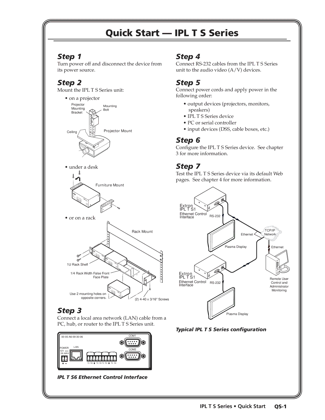
IPL T S Series specifications
The Extron IPL T SFI244 is a sophisticated control system that is designed to streamline the management and operation of audiovisual equipment in a variety of environments, including conference rooms, classrooms, and auditoriums. This model falls under the IPL T S Series, renowned for its superior performance and user-friendly interface, making it a popular choice for integrators and users alike.One of the standout features of the IPL T SFI244 is its advanced interface. It boasts an intuitive touch panel that enables users to manage multiple devices from a single control point, significantly simplifying the AV experience. The system supports a wide range of functions, including source selection, volume control, and the management of lighting and screen mechanisms. This centralized control helps to enhance collaboration and communication, particularly in educational and corporate settings.
The IPL T SFI244 integrates seamlessly with a variety of Extron technologies, including the GlobalViewer Enterprise, providing real-time monitoring and management capabilities. This web-based software solution gives administrators the ability to control AV systems remotely, ensuring optimal performance and minimizing downtime.
Another key characteristic of the IPL T SFI244 is its versatility. It incorporates various input and output options, such as HDMI, VGA, and audio connections, to accommodate different audiovisual equipment. This flexibility allows for easy integration into existing setups, catering to diverse applications and user preferences.
In terms of design, the IPL T SFI244 is engineered with reliability and durability in mind. It is equipped with features that enhance its performance in professional environments, including programmable button layouts that can be customized by users. This personalization ensures that the control system meets specific operational requirements, further enhancing the user experience.
Furthermore, the IPL T SFI244 is built with energy efficiency in mind, utilizing technologies that reduce power consumption without compromising performance. This eco-friendly approach not only supports sustainability initiatives but also contributes to long-term cost savings for organizations.
In summary, the Extron IPL T SFI244 is a comprehensive control solution that combines advanced technology, user-friendly features, and robust performance. Its ability to integrate with various AV equipment, coupled with its customizable interface and reliability, makes it an excellent choice for a wide range of applications, paving the way for more efficient and effective audiovisual management.

