Installation, cont’d

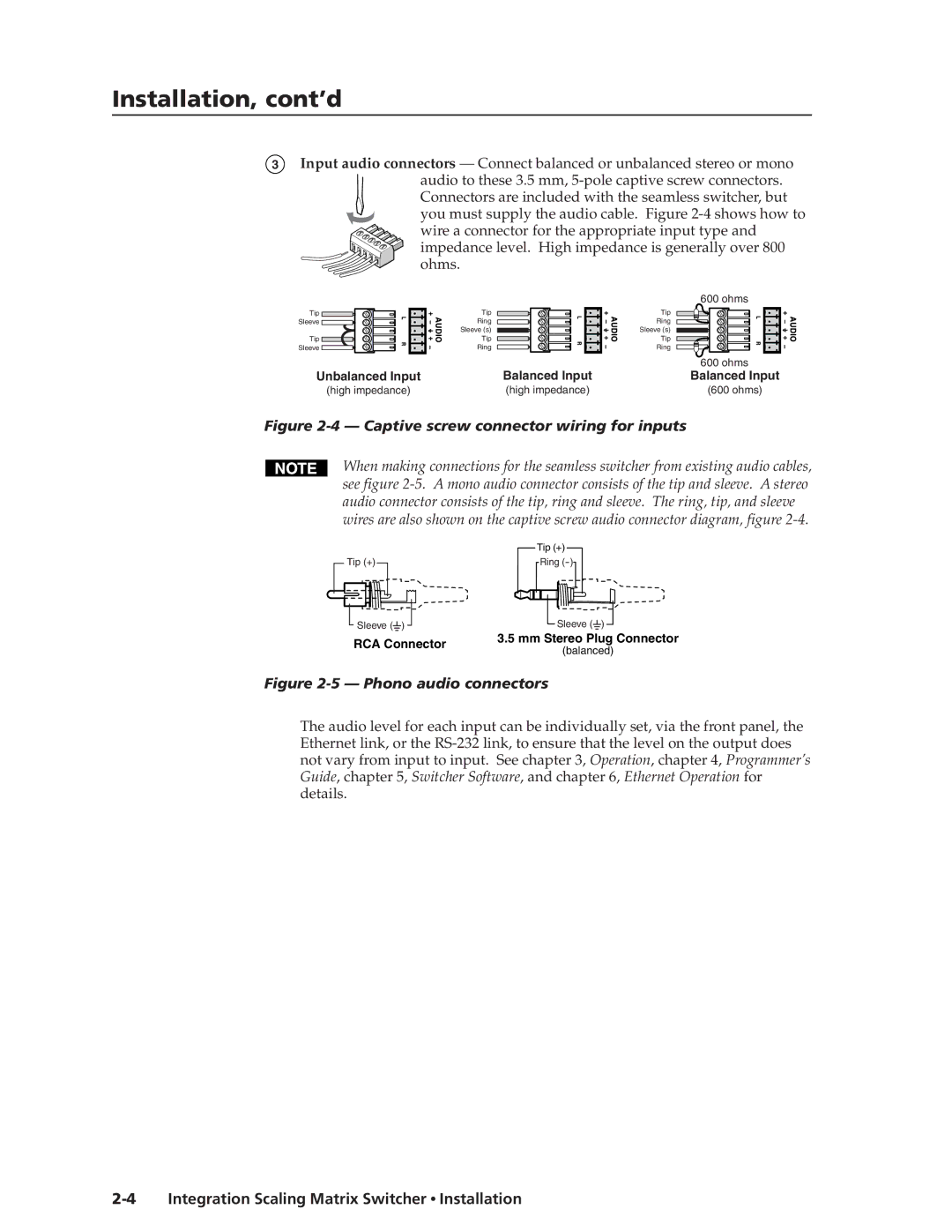
3Input audio connectors — Connect balanced or unbalanced stereo or mono

audio to these 3.5 mm, 5-pole captive screw connectors. Connectors are included with the seamless switcher, but you must supply the audio cable. Figure 2-4 shows how to wire a connector for the appropriate input type and impedance level. High impedance is generally over 800 ohms.

Tip Sleeve

Tip Sleeve

Tip

Ring

Sleeve (s)

Tip

Ring

600 ohms

Tip

Ring

Sleeve (s)

Tip

Ring


600 ohms

Unbalanced Input

Balanced Input

Balanced Input

(high impedance)

(high impedance)

(600 ohms)

Figure 2-4 — Captive screw connector wiring for inputs

When making connections for the seamless switcher from existing audio cables, see figure 2-5. A mono audio connector consists of the tip and sleeve. A stereo audio connector consists of the tip, ring and sleeve. The ring, tip, and sleeve wires are also shown on the captive screw audio connector diagram, figure 2-4.

Tip (+)

Sleeve ()

Tip (+)

Ring (-)

Sleeve ()

RCA Connector

3.5 mm Stereo Plug Connector

(balanced)


Figure 2-5 — Phono audio connectors

The audio level for each input can be individually set, via the front panel, the Ethernet link, or the RS-232 link, to ensure that the level on the output does not vary from input to input. See chapter 3, Operation, chapter 4, Programmer’s Guide, chapter 5, Switcher Software, and chapter 6, Ethernet Operation for details.

2-4 Integration Scaling Matrix Switcher Installation

Page 18
Image 18
Extron electronic ISM 182 manual Installation, cont’d, Captive screw connector wiring for inputs