ISM 482 & ISM
Integration Scaling Matrix Switchers
Instrucciones de seguridad Español
Safety Instructions English
Consignes de Sécurité Français
Sicherheitsanleitungen Deutsch
QS-1
Quick Start Integration Scaling Matrix Switcher
QS-2
Quick Start Integration Scaling Matrix Switcher, cont’d
Table of Contents
Table of Contents, cont’d
Integration Scaling Matrix Switcher Table of Contents Iii
Iv Integration Scaling Matrix Switcher Table of Contents
One
About this Manual
About the Switcher
Integration Scaling Matrix Switcher Introduction
Introductiontroduction, cont’d
Extron ISM
Introduction, cont’d
Features
Integration Scaling Matrix Switcher Introduction
Introduction, cont’d
Two
Integration Scaling Matrix Switcher Installation
Installationstallation, cont’d
Mounting the Switcher
Tabletop placement
Input connections
Cabling and Rear Panel Views
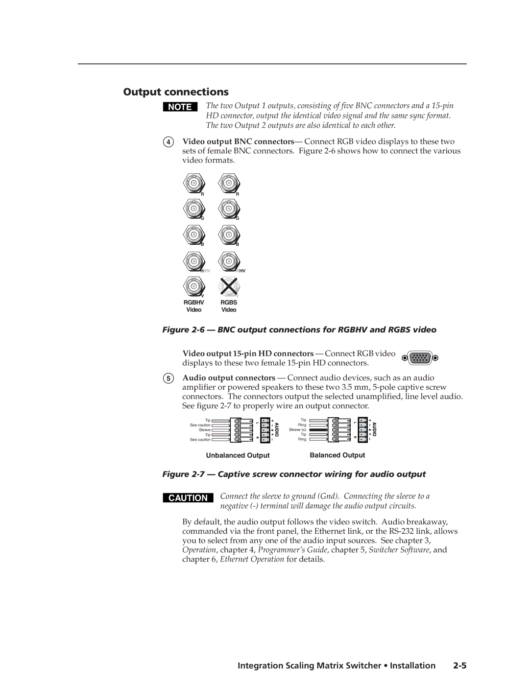
Captive screw connector wiring for inputs
Installation, cont’d
BNC output connections for Rgbhv and Rgbs video
Output connections
Ethernet connection
Cabling and RJ-45 connector wiring
Choosing a network cable
RJ-45 connector pinout tables
Wiring the network cable
RS-232 connection
Configuration
Three
Video/Audio selection button and LEDs
Front Panel Controls and Indicators
Integration Scaling Matrix Switcher Operation
Operationeration, cont’d
Input buttons, LEDs, and label window
Outputs buttons and LEDs
Front panel input label window
Operation, cont’d
Picture adjustment buttons
Black/Mute button and LEDs
LCD display
Adjustment knobs
Menu control buttons
Front Panel Operations
Power
Extron Electronics ISM 60-425-01 Version
Menu system overview
Input Configuration submenu
Video & Audio Configuration menu
Output Resolution submenu
Output Configuration menu
Sync Type and Polarity submenu
Resolution 50 Hz 56 Hz 60 Hz 75 Hz 85 Hz Lock at 50/60 Hz
Video & Audio
Advanced Configuration menu
Blanking submenu
Blue Only Mode and Edge Smoothing submenu
RGB Delay submenu
Test Pattern submenu
Reset submenu
Enhanced Mode submenu
Pixel Phase submenu
PAL Film Mode submenu
Save Preset submenu
User Presets menu
Exit menu
Erase Preset submenu
13 Picture adjustments flowchart
Picture adjustments
14 Front panel security lockout flowchart
Front panel security lockout executive mode
IP information
Optimizing the Video
Controls to position the image
Setting up a DVD source
Optimizing the Audio
Troubleshooting
General checks
Problem Cause
Specific problems
Operation, cont’d
Four
RS-232 Link
Integration Scaling Matrix Switcher Programmer’s Guide
Ethernet Link
Default address
Symbols
Input and output video type
Switcher-Initiated Messages
Power-up
Ties creation
X2 Col
Programmer’s Guide, cont’d
Switcher error responses
Host-to-Switcher Instructions
Using the command/response table
Command Ascii Command Response Additional description
Vertical size
Brightness
Contrast
Horizontal size
Vertical detail filter RGB and component video inputs
Pixel phase
Bottom blanking
Horizontal detail filter RGB and component video inputs
Test pattern
User presets
Auto Memories
Freeze
Verbose mode
Executive mode
Information requests
Resets
Command/response table for IP SIS commands
Delay times
Command/response table for special function SIS commands
Scaler settings
Edge smoothing
Enhanced mode
PAL film mode
Blue screen
Memory backup
Command Hex Command Response
Additional description
Five
Control Software for Windows
Installing the software
Ethernet protocol settings
Integration Scaling Matrix Switcher Switcher Software
If you selected a comm port, proceed to step
Using the control program
Windows Control program window
Switcher Software, cont’d
Button-Label Generator
Using the help program
Using the software
Installing the software
Six
EthernetOperation,cont’d
Integration Scaling Matrix Switcher Ethernet Operation
Load the Startup Control
Control
Create a tie
Change the RGB delay
Ethernet Operation, cont’d
Control
Preview the scan rate
Executive mode
Freeze the output
Output a test pattern
System Configuration
System Configuration
ISM Name field
Administration fields
ISM IP Settings fields
ISM IP Address field
File Management
File Management
I/O Configuration
Input configuration
Output resolution, rate, sync format, and polarity
Output rate
Output resolution
Output polarity
Output format
AAppendix a
Ethernet Connection, cont’d
Integration Scaling Matrix Switcher Ethernet Connection
Ping to determine the Web IP address
Ping to determine the switcher’s IP address
Telnet tips
Connect as a Telnet client
Open
Close
Escape character and Esc key
Local echo
Set carriage return-line feed
Ethernet Connection, cont’d
AppendixBB
Integration Scaling Matrix Switcher Reference Information
Specifications
Audio
Part Numbers
Optional accessories
Cables and connectors
Reference Information, cont’d
Plenum BNC-5 Mini HR Cable
Assorted connectors BNC connectors
BNC-4 Mini HR Cable
BNC-5 Mini HR Cable
Firmware Upgrade Installation
Figure B-1 Removing the ISM cover
Button Labels
Integration Scaling Matrix Switcher Reference Information
Reference Information, cont’d
FCC Class B Notice
Extron Electronics, USA