•Color/Tint: Color adjusts within a range from 0 to 127. Tint adjusts within a range from 0 to 255.
•Brightness/Contrast: The range for both adjustments is 0 to 63.
•Size: Observe the display and turn the Adjust ![]()
![]() knob to increase or decrease the horizontal size of the image. Turn the Adjust
knob to increase or decrease the horizontal size of the image. Turn the Adjust ![]() knob to increase or decrease the vertical size of the image. The adjustment range depends on the input rate applied and the output resolution selected.
knob to increase or decrease the vertical size of the image. The adjustment range depends on the input rate applied and the output resolution selected.
•Center: Observe the display and turn the Adjust ![]()
![]() knob to center the image horizontally or the Adjust
knob to center the image horizontally or the Adjust ![]() knob to center the image vertically. The adjustment range depends on the input rate applied and the selected output resolution selected.
knob to center the image vertically. The adjustment range depends on the input rate applied and the selected output resolution selected.
•Horizontal and vertical filter (RGB or component video input): Horizontal (Horz) adjusts within a range from 0 to 3.
Vertical (Vert) adjusts within a range from 0 to 7.
•Filter
4.Repeat steps 2 and 3 for each image adjustment to be made for that output.
5. | If you want to set picture adjustment on the another tie, press the another |
| input button or the other output button. |
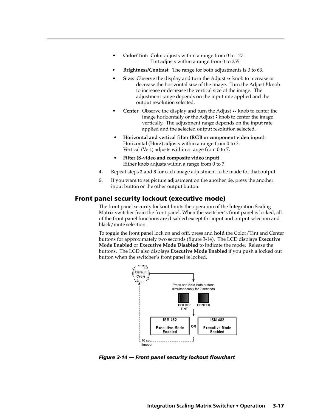
Front panel security lockout (executive mode)
The front panel security lockout limits the operation of the Integration Scaling Matrix switcher from the front panel. When the switcher’s front panel is locked, all of the front panel functions are disabled except for input and output selection and black/mute selection.
To toggle the front panel lock on and offf, press and hold the Color/Tint and Center buttons for approximately two seconds (figure
Default
Cycle
Press and hold both buttons simultaneously for 2 seconds
COLOR/ |
|
| CENTER |
TINT |
|
|
|
ISM 482 |
|
| ISM 482 |
|
| ||
Executive Mode | OR | Executive Mode | |
Enabled |
|
| Enabled |
10sec. timeout