Installation, cont’d
2. | Cable the rear of the transmitter before fastening the AAP |
| module to the AAP frame. |
3. | Insert each of the AAP module’s screws through the holes |
| in the AAP frame. Secure the transmitter to the frame with |
| the provided captive washers and |
4. | Install the AAP frame as appropriate to the type of frame. |
| Figure |
| in an AAP 102 wall mounting frame and the frame being |
| installed in a wall box. |
Panel Features and Connections
Transmitter input connections
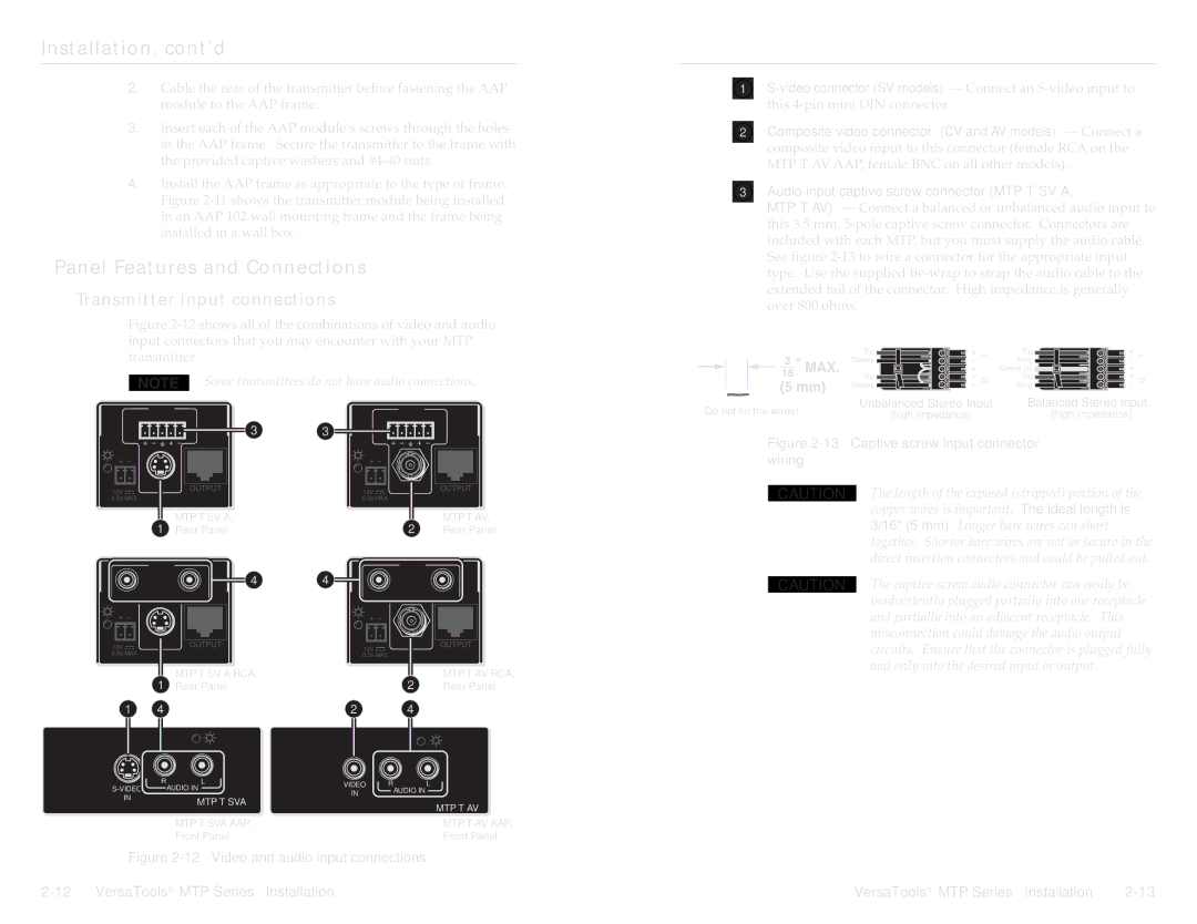
Figure 2-12 shows all of the combinations of video and audio input connectors that you may encounter with your MTP transmitter.
Some transmitters do not have audio connections.
| INPUT |
| INPUT |
L | R | L | R |
3 | 3 |
OUTPUT | 12V | VIDEO | OUTPUT | |
12V |
|
|
| |
0.5a MAX | MTP T SV A | 0.5a MAX |
| MTP T AV |
|
|
|
| 1 | MTP T SV A, |
|
| 2 | MTP T AV, |
| Rear Panel |
|
| Rear Panel | ||
| INPUT |
|
|
| INPUT |
|
|
| 4 | 4 |
|
|
|
L |
| R |
| L |
| R |
12V |
| 12V | VIDEO | OUTPUT | ||
|
|
|
|
| ||
0.5a MAX | MTP T SV A RCA |
| 0.5a MAX | MTP T AV RCA | ||
|
|
| ||||
| 1 | MTP T SV A RCA, |
|
| 2 | MTP T AV RCA, |
| Rear Panel |
|
| Rear Panel | ||
1 | 4 |
| 2 |
| 4 |
|
R | L | VIDEO | R | L | |
AUDIO IN | |||||
IN |
| AUDIO IN | |||
IN | MTP T SVA |
|
| ||
|
|
| |||
|
|
| MTP T AV | ||
|
|
|
| ||
| MTP T SVA AAP, |
|
| MTP T AV AAP, | |
| Front Panel |
|
| Front Panel |
Figure 2-12 — Video and audio input connections
1
2Composite video connector (CV and AV models) — Connect a composite video input to this connector (female RCA on the MTP T AV AAP, female BNC on all other models).
3Audio input captive screw connector (MTP T SV A,
MTP T AV) — Connect a balanced or unbalanced audio input to this 3.5 mm,
Tip | L | Tip | L | |
Sleeve | Ring | |||
|
| |||
|
| Sleeve (s) |
| |
Tip | R | Tip | R | |
Sleeve | Ring | |||
|
|
Do not tin the wires! | Unbalanced Stereo Input | Balanced Stereo Input | ||
(high impedance) | (high impedance) | |||
|
| |||
Figure | ||||
wiring |
|
| ||
|
| The length of the exposed (stripped) portion of the | ||
| CAUTION | |||
|
| copper wires is important. The ideal length is | ||
|
| 3/16" (5 mm). Longer bare wires can short | ||
|
| together. Shorter bare wires are not as secure in the | ||
|
| direct insertion connectors and could be pulled out. | ||
|
| The captive screw audio connector can easily be | ||
| CAUTION | |||
|
| inadvertently plugged partially into one receptacle | ||
and partially into an adjacent receptacle. This misconnection could damage the audio output circuits. Ensure that the connector is plugged fully and only into the desired input or output.
VersaTools® MTP Series • Installation