Installation, cont’d
TP cable termination
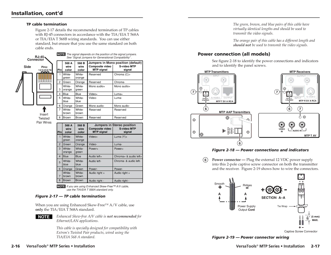
Figure 2-17 details the recommended termination of TP cables with RJ-45 connectors in accordance with the TIA/EIA T 568A or TIA/EIA T 568B wiring standards. You can use either standard, but ensure that you use the same standard on both cable ends.
The green, brown, and blue pairs of this cable have virtually identical lengths and should be used to transmit the video signals.
The orange pair of this cable has a different length and should not be used to transmit the video signals.
RJ-45
Connector
Side Pins:
1 2 3 4 5 6 7 8
Insert
Twisted
Pair Wires
NOTE The signal depends on the position of the signal jumpers. See “Signal Jumpers for Generational Compatibility” .
| 568 A | 568 B | Jumpers in Mono position (default) | |
| wire | wire | Composite video | |
Pin | color | color | MTP signal | signal |
1 | White- | White- | Reserved | Chroma (C)+ |
| green | orange |
|
|
|
|
|
|
|
2 | Green | Orange | Reserved | Chroma- |
| White- | White- | Mono audio+ | Mono audio+ |
3 | orange | green |
|
|
|
|
|
|
|
4 | Blue | Blue | Video+ | Luma+ |
5 | White- | White- | Video- | Luma- |
| blue | blue |
|
|
|
|
|
|
|
6 | Orange | Green | Mono audio- | Mono audio- |
7 | White- | White- | Reserved | Reserved |
| brown | brown |
|
|
|
|
|
|
|
8 | Brown | Brown | Reserved | Reserved |
|
|
|
| |
| 568 A | 568 B | Jumpers in Stereo position | |
| wire | wire | Composite video | |
Pin | color | color | MTP signal | signal |
1 | White- | White- | Video+ | Luma (Y)+ |
| green | orange |
|
|
2 | Green | Orange | Video- | Luma- |
3 | White- | White- | Power+ | Power+ |
| orange | green |
|
|
4 | Blue | Blue | Audio left+ | Chroma+ & audio left+ |
5 | White- | White- | Audio left- | Chroma- & audio left- |
| blue | blue |
|
|
6 | Orange | Green | Power- | Power- |
| White- | White- | Audio right + | Audio right + |
7 | brown | brown |
|
|
8 | Brown | Brown | Audio right - | Audio right - |
NOTE If you are using Enhanced
Power connection (all models)
See figure
MTP Transmitters |
|
| MTP Receivers | |||
| INPUT |
|
|
| OUTPUT | |
L | R |
|
| L |
| R |
7 |
|
| 7 |
|
|
|
12V |
| 12V |
| INPUT | ||
|
|
| ||||
0.5a MAX | MTP T SV A RCA | 0.5a | MAX | MTP R SV A RCA | ||
|
|
|
|
| ||
6 | MTP AAP Transmitters | 6 | 7 |
| ||
|
|
|
|
| ||
| OUTPUT |
|
|
|
|
|
| POWER 12V 0.5AMAX | −+ | VIDEO | R |
| L |
|
|
| IN | AUDIO IN |
| |
|
|
|
|
|
| MTP T AV |
6
Figure 2-18 — Power connections and indicators
6Power connector — Plug the external 12 VDC power supply into this
SmoothRidges
Figure 2-17 — TP cable termination
When you are using Enhanced
Enhanced
Ethernet/LAN applications.
This cable is specially designed for compatibility with
Extron’s Twisted Pair products, wired using the
TIA/EIA 568 A standard.
A | A | SECTION |
|
| |
| Power Supply | Tie Wrap |
| Output Cord |
|
3 ![]()
![]() 5
5 ![]()
![]()
Captive Screw Connector
Figure 2-19 — Power connector wiring
VersaTools® MTP Series • Installation