Installation
CAUTION Installation and service must be performed by authorized personnel only.
Signal Jumpers for Generational Compatibility
Over time, the MTPs have been redesigned, affecting the signal content of the TP cable wire pairs, changing the audio from stereo to mono, and eliminating the remote power capability. The
Shift the new transmitter’s and/or receiver’s jumpers if:
•Your installation mixes a transmitter and receiver from different generations.
•You want the units to transmit stereo audio.
•You want one unit to remotely power another.
Use the table below to identify the generation (revision level) of the transmitter and receiver in your installation. If any of the above scenarios are true, reconfigure the units’ jumpers before mounting the units.
Only the new generation units have these jumpers.
Transmitter | Old generation | New generation |
| part # | part # |
MTP T SV | ||
MTP T SV A | ||
MTP T SV A RCA | ||
MTP T SV A AAP | ||
MTP T CV | ||
MTP T AV | ||
MTP T AV RCA | ||
MTP T AV AAP |
Receiver | Old generation | New generation |
| part # | part # |
MTP R SV | ||
MTP R SV A | ||
MTP R SV A RCA | ||
MTP R CV | ||
MTP R AV | ||
MTP R AV RCA |
Setting the jumpers on non AAP models
1. Remove and retain the four screws (two on each side of the unit) that secure the cover to the MTP (figure
Figure 2-1 — Removing the MTP cover
2. For the receiver, slide the cover slightly forward to clear the front panel adjustment knobs.
3. | Lift the cover straight up. |
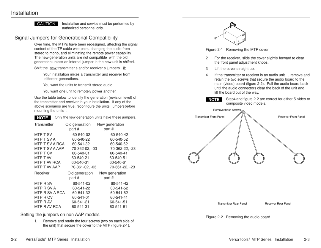
4. If the transmitter or receiver is an audio unit, remove and retain the two screws that secure the audio board to the main (video) board (figure
Step 4 and figure 2-2 are correct for either S-video or composite video models.
Remove these screws.
Transmitter Front Panel | Receiver Front Panel |
Transmitter Rear Panel | Receiver Rear Panel |
Figure 2-2 — Removing the audio board
VersaTools® MTP Series • Installation | VersaTools® MTP Series • Installation |