Installation, cont’d
When making connections for the MTP from existing audio cables, see figure
Transmitter/receiver throughput connections
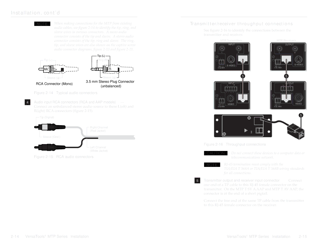
See figure
connector consists of the tip, ring and sleeve. The ring, tip, and sleeve wires are also shown on the captive screw audio connector diagrams, figure
MTP Transmitters
INPUT
LR
MTP Receivers
OUTPUT
LR
Tip (+)
Tip (L)
Ring (R)
|
|
|
|
|
|
|
|
|
|
|
|
12V |
|
| |||
| |||||
0.5a MAX | MTP T SV A RCA | ||||
|
|
|
| ||
12V |
| INPUT | |
0.5a | MAX | MTP R SV A RCA | |
|
| ||
Sleeve (![]() )
)
Sleeve (![]() )
)
5
5 |
3.5 mm Stereo Plug Connector
RCA Connector (Mono)
(unbalanced)
Figure 2-14 — Typical audio connectors
4Audio input RCA connectors (RCA and AAP models) — Connect an unbalanced stereo audio source to these L(eft) and R(ight) RCA connectors (figure
INPUT
L R
|
|
|
| VIDEO | OUTPUT |
12V |
|
| |||
| |||||
0.5a MAX |
| MTP T AV | |||
|
|
|
|
| |
|
| OUTPUT |
|
| L | R |
|
12V | INPUT | VIDEO | |
| |||
0.5a | MAX |
| MTP R AV |
|
|
| |
Tip (Signal)
Sleeve (Gnd )
Right Channel (Red Jacket)
Left Channel (White Jacket)
5 OUTPUT ![]()
![]()
− + POWER 12V 0.5A MAX![]()
![]()
Figure 2-16 — Throughput connections
CAUTION Do not connect these devices to a computer data or
Figure 2-15 — RCA audio connectors
telecommunications network.
TIA/EIA T 568A or TIA/EIA T 568B wiring standards for all connections.
5Transmitter output and receiver input connector — Connect one end of a TP cable to this
Connect the free end of the same TP cable from the transmitter to this
VersaTools® MTP Series • Installation |
