Operation
Front Panel Features
MTP R Composite Video | MTP R | |||
Receiver Front Panel |
| Front Panel |
|
|
GAIN | SHARP | Y GAIN | C GAIN | SHARP |
1 | 3 | 2 | 1 | 3 | 3 | 2 |
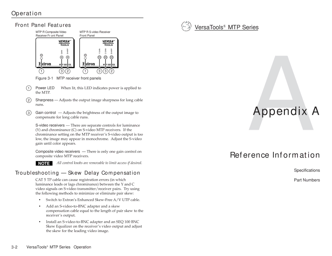
Figure 3-1 — MTP receiver front panels
1Power LED — When lit, this LED indicates power is applied to the MTP.
2Sharpness — Adjusts the output image sharpness for long cable runs.
3Gain control — Adjusts the brightness of the output image to compensate for long cable runs.
(Y) and chrominance (C) on
Composite video receivers — There is only one gain control on composite video MTP receivers.
All control knobs are removable to limit access if desired.
Troubleshooting — Skew Delay Compensation
CAT 5 TP cable can cause registration errors (in which luminance leads or lags chrominance) between the Y and C video signals on
•Switch to Extron’s Enhanced
•Add an
•Install an

 VersaTools® MTP Series
AAppendix A
Reference Information
Specifications
Part Numbers