Installation and Operation, cont’d
Front Panel Controls and Indicators
|
|
|
|
|
|
|
|
|
|
| 7 |
|
|
|
|
|
|
|
| 6 |
|
|
| ||
|
|
|
|
|
|
|
|
|
|
|
|
|
|
|
|
|
|
|
|
|
|
|
| RATE | |
AUTO |
|
|
|
|
|
|
|
|
|
|
|
|
|
|
|
|
|
|
|
|
|
|
| NOT | |
|
|
|
|
|
|
|
|
|
|
|
|
|
|
|
|
|
|
|
|
|
|
| |||
|
|
|
|
|
|
|
|
|
|
|
|
|
|
|
|
|
|
|
|
|
|
| |||
|
|
|
|
|
|
|
|
|
|
|
|
|
|
|
|
|
|
|
|
|
|
| RECOGNIZED | ||
SWITCH |
|
|
|
| 1 |
|
| 2 |
|
| 3 |
|
|
| 4 |
|
|
|
| 2.97 Gbps | |||||
ACTIVE |
|
|
|
|
|
|
|
|
|
|
|
|
|
|
|
|
|
|
|
|
|
|
| 1.485 Gbps | |
|
| MODE | NORMAL |
| AUTO |
|
|
|
|
|
|
|
|
| 270 Mbps | ||||||||||
|
|
|
|
|
|
|
|
|
|
|
|
|
|
|
|
|
|
|
|
|
|
|
| SW4 3G | |
|
|
|
|
|
|
|
|
|
|
|
|
|
|
|
|
|
|
|
|
|
|
|
| ||
|
|
|
|
|
|
|
|
|
|
|
|
|
|
|
|
|
|
|
|
|
|
|
|
|
|
|
|
|
|
|
|
|
|
|
|
|
|
|
|
|
|
|
|
|
|
|
|
|
| ||
|
|
|
|
|
|
|
|
|
|
|
|
|
|
|
|
|
|
|
|
|
|
|
| ||
1 | 2 |
|
|
| 3 |
|
| 4 |
|
| 5 |
|
|
|
|
|
|
|
|
| |||||
| SW4 3G |
|
|
|
|
| |||||||||||||||||||
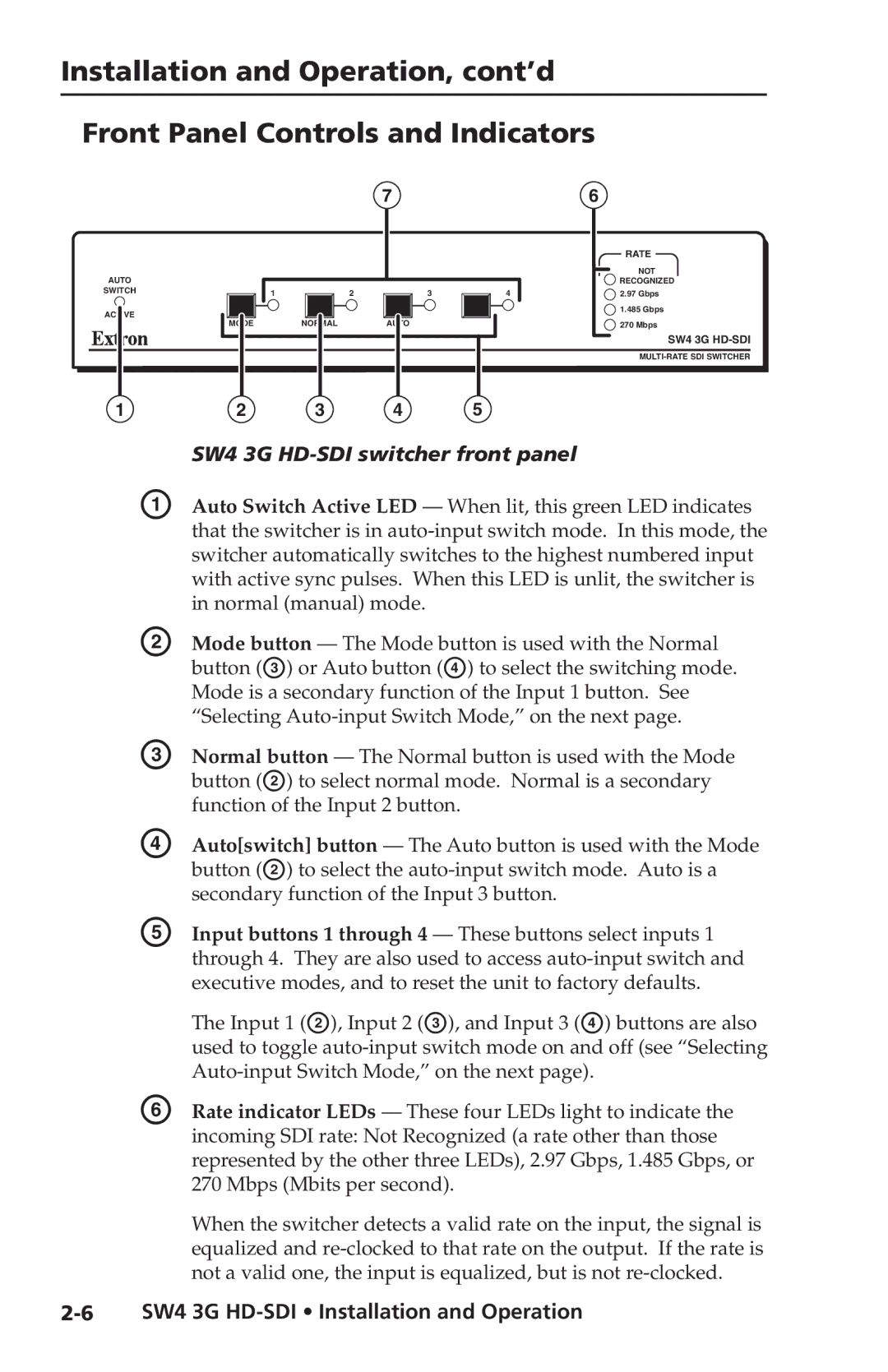
A | Auto Switch Active LED — When lit, this green LED indicates | ||||||||||||||||||||||||
| that the switcher is in | ||||||||||||||||||||||||
| switcher automatically switches to the highest numbered input | ||||||||||||||||||||||||
| with active sync pulses. When this LED is unlit, the switcher is | ||||||||||||||||||||||||
| in normal (manual) mode. |
|
|
|
|
|
|
|
|
|
|
| |||||||||||||
B | Mode button — The Mode button is used with the Normal | ||||||||||||||||||||||||
| button (C) or Auto button (D) to select the switching mode. | ||||||||||||||||||||||||
| Mode is a secondary function of the Input 1 button. See | ||||||||||||||||||||||||
| “Selecting | ||||||||||||||||||||||||
C | Normal button — The Normal button is used with the Mode | ||||||||||||||||||||||||
| button (B) to select normal mode. Normal is a secondary | ||||||||||||||||||||||||
| function of the Input 2 button. |
|
|
|
|
|
|
|
|
|
|
| |||||||||||||
D | Auto[switch] button — The Auto button is used with the Mode | ||||||||||||||||||||||||
| button (B) to select the | ||||||||||||||||||||||||
| secondary function of the Input 3 button. |
|
|
|
|
| |||||||||||||||||||
E | Input buttons 1 through 4 — These buttons select inputs 1 | ||||||||||||||||||||||||
| through 4. They are also used to access | ||||||||||||||||||||||||
executive modes, and to reset the unit to factory defaults.
| The Input 1 (B), Input 2 (C), and Input 3 (D) buttons are also |
| used to toggle |
| |
F | Rate indicator LEDs — These four LEDs light to indicate the |
| incoming SDI rate: Not Recognized (a rate other than those |
| represented by the other three LEDs), 2.97 Gbps, 1.485 Gbps, or |
| 270 Mbps (Mbits per second). |
| When the switcher detects a valid rate on the input, the signal is |
| equalized and |
| not a valid one, the input is equalized, but is not |
