Installation and Operation, cont’d
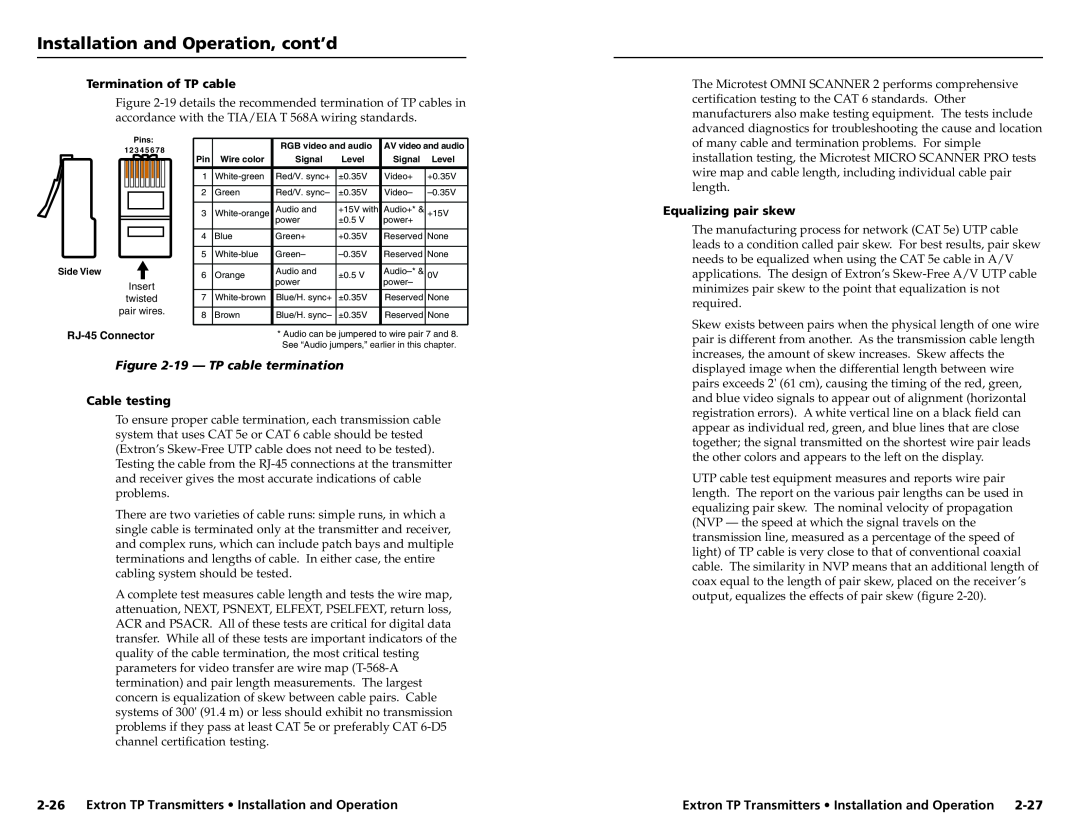
Termination of TP cable
Figure
The Microtest OMNI SCANNER 2 performs comprehensive certification testing to the CAT 6 standards. Other manufacturers also make testing equipment. The tests include advanced diagnostics for troubleshooting the cause and location
Pins:
1 2 34 5 6 7 8
Side View
Insert
twisted pair wires.
|
| RGB video and audio | AV video and audio | ||
Pin | Wire color | Signal | Level | Signal | Level |
|
|
|
|
|
|
1 | Red/V. sync+ | ±0.35V | Video+ | +0.35V | |
|
|
|
|
|
|
2 | Green | Red/V. sync– | ±0.35V | Video– | |
|
|
|
|
|
|
3 | Audio and | +15V with | Audio+* & | +15V | |
|
| power | ±0.5 V | power+ |
|
|
|
|
|
|
|
4 | Blue | Green+ | +0.35V | Reserved | None |
|
|
|
|
|
|
5 | Green– | Reserved | None | ||
|
|
|
|
|
|
6 | Orange | Audio and | ±0.5 V | 0V | |
|
| power |
| power– |
|
7 | Blue/H. sync+ | ±0.35V | Reserved | None | |
|
|
|
|
|
|
8 | Brown | Blue/H. sync– | ±0.35V | Reserved | None |
|
|
|
|
|
|
*Audio can be jumpered to wire pair 7 and 8. See “Audio jumpers,” earlier in this chapter.
of many cable and termination problems. For simple installation testing, the Microtest MICRO SCANNER PRO tests wire map and cable length, including individual cable pair length.
Equalizing pair skew
The manufacturing process for network (CAT 5e) UTP cable leads to a condition called pair skew. For best results, pair skew needs to be equalized when using the CAT 5e cable in A/V applications. The design of Extron’s
Skew exists between pairs when the physical length of one wire pair is different from another. As the transmission cable length increases, the amount of skew increases. Skew affects the
Figure 2-19 — TP cable termination
Cable testing
To ensure proper cable termination, each transmission cable system that uses CAT 5e or CAT 6 cable should be tested (Extron’s
There are two varieties of cable runs: simple runs, in which a single cable is terminated only at the transmitter and receiver, and complex runs, which can include patch bays and multiple terminations and lengths of cable. In either case, the entire cabling system should be tested.
A complete test measures cable length and tests the wire map, attenuation, NEXT, PSNEXT, ELFEXT, PSELFEXT, return loss, ACR and PSACR. All of these tests are critical for digital data transfer. While all of these tests are important indicators of the quality of the cable termination, the most critical testing parameters for video transfer are wire map
displayed image when the differential length between wire pairs exceeds 2' (61 cm), causing the timing of the red, green, and blue video signals to appear out of alignment (horizontal registration errors). A white vertical line on a black field can appear as individual red, green, and blue lines that are close together; the signal transmitted on the shortest wire pair leads the other colors and appears to the left on the display.
UTP cable test equipment measures and reports wire pair length. The report on the various pair lengths can be used in equalizing pair skew. The nominal velocity of propagation (NVP — the speed at which the signal travels on the transmission line, measured as a percentage of the speed of light) of TP cable is very close to that of conventional coaxial cable. The similarity in NVP means that an additional length of coax equal to the length of pair skew, placed on the receiver’s output, equalizes the effects of pair skew (figure
Extron TP Transmitters • Installation and Operation |