Installation and Operation, cont’d
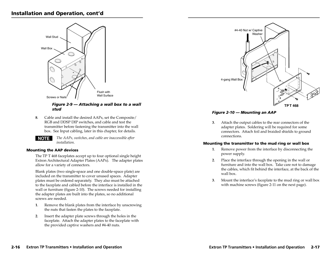
Wall Stud
Wall Box
Screws or Nails
Flush with Wall Surface
R | T 46 | 8 |
MONITO |
| |
| TP |
|
INPUT |
|
|
Figure 2-9 — Attaching a wall box to a wall stud
8. Cable and install the desired AAPs, set the Composite/ RGB and DDSP DIP switches, and cable and test the transmitter before fastening the transmitter into the wall box. See Input cabling, later in this chapter, for details.
The AAPs, switches, and cable are inaccessible after installation.
Mounting the AAP devices
The TP T 468 faceplates accept up to four optional single height Extron Architectural Adapter Plates (AAPs). The adapter plates allow for a variety of connectors.
Blank plates (two
1. | Remove the blank plates from the interface by unscrewing |
| the nuts that fasten the plates to the faceplate. |
2. | Insert the adapter plate screws through the holes in the |
| faceplate. Attach the adapter plates to the faceplate with |
| the provided captive washers and |
TP T 468
Figure 2-10 — Mounting an AAP
3. | Attach the output cables to the rear connectors of the |
| adapter plates. Soldering will be required for some |
| connectors. Attach foil and braided shields to ground |
| connections. |
Mounting the transmitter to the mud ring or wall box | |
1. | Remove power from the interface by disconnecting the |
| power supply. |
2. | Place the interface through the opening in the wall or |
| furniture and into the wall box. Take care not to damage |
| the cables, which fit behind the interface, at the back of the |
| wall box. |
3. | Mount the interface’s faceplate to the mud ring or wall box |
| with machine screws (figure |
Extron TP Transmitters • Installation and Operation |