Dual Display Multimeter
Limited Warranty & Limitation of Liability
Declaration of the Manufacturer or Importer
Page
Table of Contents
Applications
Appendices
Page
List of Tables
Page
List of Figures
Introduction
Introducing the Fluke 45 Dual Display Multimeter
Model Accessories Description
Options and Accessories
Where to go from Here
Maintenance Appendices
Page
Multimeter Safety
Page
Introduction
Getting Started
Front Panel
Using the Pushbuttons
Turning the Meter on
Summary of Basic Pushbutton Operations
Taking Some Basic Measurements
Selecting a Measurement Range
Automatic Input Terminal Selection
Measuring Current
Diode/Continuity Testing
Measuring Voltage, Resistance, or Frequency
Freq
Continuity Testing
Operating the Meter Under Battery Power Optional
Rack Mounting
Page
Operating the Meter From the Front Panel
Front Panel Operations
Secondary Display
Display
Primary Display
Remote SMF
Input Terminals
Input Terminals
Selecting a Measurement Function
Ranging
Autoranging
Input Limits
Function Buttons
Slow Reading Rate Range Full Scale
Ohms Ranges and Full Scale Values Fast Reading Rate
Medium Reading Rate Range Full Scale
Frequency Ranges and Full Scale Values Slow and Medium
Frequency Ranging
Measuring Frequency
Manual Ranging
Frequency Measurement Rates
Measuring Frequency of Current 100 mA and 10A Inputs
Frequency Sensitivity Selection
Frequency Measurement Rates
Maximim Input Voltage
Selecting a Function Modifier
Maximum Sinewave Inputs for Frequency Measurements Range
REL Relative Readings Modifier
Function Modifier Selection Buttons
DB Decibels and Audio Power Modifier
Reference Impedances in Ohms
MN MX Minimum Maximum Modifier
Using Function Modifiers in Combination
Hold Touch Hold Modifier
Using the SButton
Selecting a Measurement Rate Rate
Pushbuttons
10. SButton Operations
Using The Compare Comp Function
List and Number Editors
Using the List Editor
Using the Number Editor
Changing the Power-Up Configuration
Power-Up Configuration
Factory Settings of Power-Up Configuration
Calibration
13. Power-Up Configuration Set at Factory Parameter
Configurations
Using the Dual Display
Applications
Using Measurement Functions in Combination
Dual Display Showing Volts AC and Frequency
Sample Dual Display Applications Primary Display
Applications
DC Voltage and DC Current Measurement on Input Signal
Response Times
How the Meter Makes Dual Display Measurements
Slow Rate Auto Single Range1 Range2 Medium Rate Fast Rate
Slow Med Fast
Update Rate in the Dual Display Mode
External Trigger
Thermal Voltages
All
When Measuring Resistance
Two-Wire Configuration
True RMS Measurements
Correcting for Test Lead Resistance
Waveform Comparison True RMS vs. Average-Responding Meters
Effects of Internal Noise in AC Measurements
Calculated AC + DC RMS Measurements
True RMS Measurements
Page
Local and Remote Operations
Computer Interfaces
Setting Communication Parameters RS-232
Factory Settings of RS-232 Communication Parameters
Factory Setting
Preparing the Meter for Operations via the RS-232 Interface
RS-232 Print-Only Mode
Device Clear Using C Cntrl C
Cabling the Meter to a Host or Printer RS-232
Character Echoing and Deletion
RS-232 Prompts
Installing the IEEE-488 Interface
Preparing the Meter to be Operated via IEEE-488 Interface
IEEE-488 Operating Limitations
Enabling the IEEE-488 Interface
Getting Started With An Installation Test
Installation Test for RS-232 Operations
Installation Test for IEEE-488 Operations
Cabling the Meter to a Host
How the Meter Processes Input
If Test Fails
Input Strings
Input Terminators
Sending Numeric Values to the Meter
Sending Command Strings to the Meter
Typical IEEE-488 Input Strings
Page
Typical IEEE-488 Input Strings
External Triggering from the Front Panel
How the Meter Processes Output
Triggering Output
Setting the Trigger Type Configuration
External Triggering via the Computer Interface
Service Requests IEEE-488 Only and Status Registers
Settling Delay
Trigger Type
Rear Trigger
Read Command
Write Command
Enable Register
Status Register Summary
ESB MAV 3 2 1
Event Status and Event Status Enable Registers
Event Status and Event Status Enable Registers
Status Byte Register
Reading the Status Byte Register
Description of Bits in ESR and ESE Bit No Name
True Set to 1 Conditions
True Set to 1 Condition
Service Request Enable Register
Description of Bits in the Status Byte Register Bit No Name
Computer Interface Command Set
IEEE-488 Capabilities and Common Commands
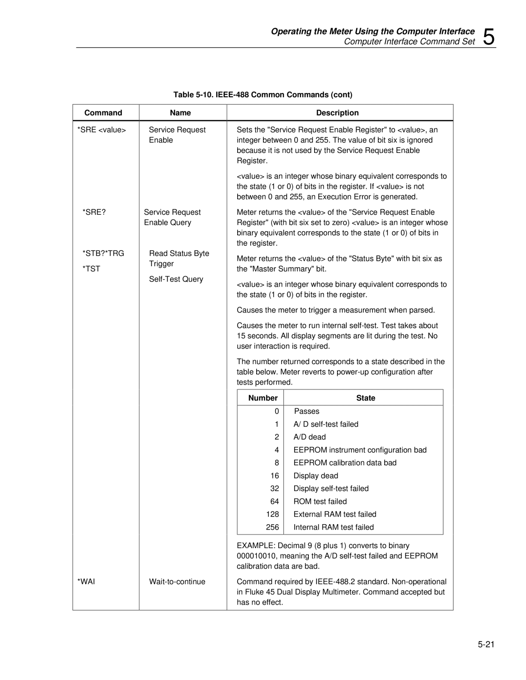
IEEE-488 Common Commands
IEEE-488 Interface Function Subsets
10. IEEE-488 Common Commands
Number State
11. Function Commands and Queries Primary Secondary Display
Function Commands and Queries
Function Modifier Commands and Queries
Command
12. Function Modifier Commands and Queries Description
12A. Reference Impedance Values Ref Impedance
Value Ref Impedance
MIN
Range and Measurement Rate Commands and Queries
Ohms Range
Current Range
Frequency Range
14. Measurement Queries Description
13. Range and Measurement Rate Commands and Queries
Measurement Queries
Compare Commands and Queries
Trigger Configuration Commands
15. Compare Commands and Queries Description
16. Trigger Configuration Commands Description
Miscellaneous Commands and Queries
17. Miscellaneous Commands and Queries Description
16A. Measurement Units Output with Format
Measurement Function
RS-232 Remote/Local Configurations
18. Remote/Local Configuration Commands Description
Sample Program Using the RS-232 Computer Interface
Sample Program for RS-232 Computer Interface
Sample Programs Using the IEEE-488 Computer Interface
Sample Programs for IEEE-488 Computer Interface
Aam25s.tif
Aam26s.tif
Aam27s.tif
Operating the Meter Using the Computer Interface
Introduction Cleaning
Line Fuse
Testing Current Input Fuses
Current Input Fuses
Front Panel Input Terminal
Replacing the 100 mA Input Fuse
Replacing the 10 a Input Fuse
Performance Tests
Self-Test Diagnostics and Error Codes
Error No Self-Test Error Codes Meaning
Service
Input Level
Frequency
Min Max
Using decades 300 Ω Short 30 kΩ
Replacement Parts
Replacement Parts
Performance Tests for mA Current Functions
Min Max 29.982 30.018
TM1 TM2 TM3 TM4 TM5
Appendices
Page
Response Times
Display Counts and Reading Rates
RS-232 and IEEE-488 Reading Transfer Rates
Normal Mode Rejection Ratio
Common Mode Rejection Ratio
DC Voltage
Input Impedance
Decibel Resolution
True RMS AC Voltage, AC-Coupled
Maximum Input
Accuracy
AC + DC Voltage Accuracy
Maximum Crest Factor Common Mode Rejection Ratio
Decibel Reference Resistance
DC Current
AC Current
Range Slow
Accuracy
Maximum Crest Factor Maximum Input
RangeFrequency Slow Accuracy Medium Fast
Ohms
Diode Test/Continuity
Sensitivity Level of AC Current
Frequency
Sensitivity of AC Voltage
Environmental
General
Options
ASCII/IEEE-488 Bus Codes
Page
ASCII/IEEE-488 Bus Codes B
Page
IEEE-488.2 Device Documentation Requirements
Implementation of Ieee Standard
Numeric Response Data
Measurement
*RDT and *RAT? commands are not implemented