Victoreen 875
Operators Manual
Thickness | 0.015 inch (0.38 mm) nominal |
Outer Diameter | 0.217 inch (5.51 mm) nominal |
Impedance | 75 ohms nominal |
Capacitance | 22 pf/ft nominal |
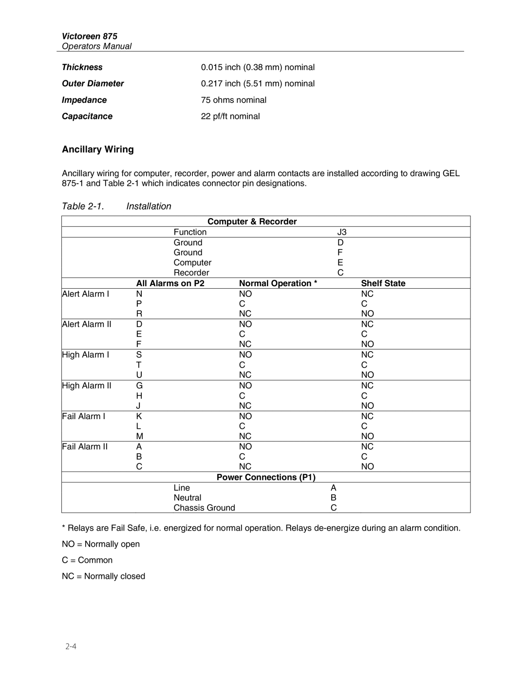
Ancillary Wiring
Ancillary wiring for computer, recorder, power and alarm contacts are installed according to drawing GEL
Table | Installation |
|
|
|
|
| Computer & Recorder |
|
| Function | J3 |
| Ground | D |
| Ground | F |
| Computer | E |
| Recorder | C |
| All Alarms on P2 | Normal Operation * | Shelf State |
Alert Alarm I | N | NO | NC |
| P | C | C |
| R | NC | NO |
Alert Alarm II | D | NO | NC |
| E | C | C |
| F | NC | NO |
High Alarm I | S | NO | NC |
| T | C | C |
| U | NC | NO |
High Alarm II | G | NO | NC |
| H | C | C |
| J | NC | NO |
Fail Alarm I | K | NO | NC |
| L | C | C |
| M | NC | NO |
Fail Alarm II | A | NO | NC |
| B | C | C |
| C | NC | NO |
Power Connections (P1)
Line | A |
Neutral | B |
Chassis Ground | C |
*Relays are Fail Safe, i.e. energized for normal operation. Relays
C = Common
NC = Normally closed