Model LM16 [Names and functions]
2
6
9
10
11
12
16
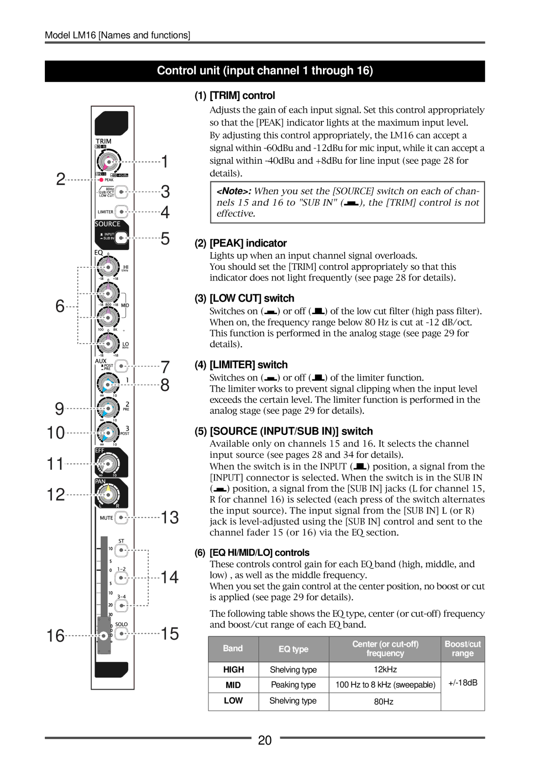
Control unit (input channel 1 through 16)
(1) [TRIM] control
Adjusts the gain of each input signal. Set this control appropriately so that the [PEAK] indicator lights at the maximum input level.
By adjusting this control appropriately, the LM16 can accept a signal within
1 |
| signal within | |||||||||||||||||||||||
|
| ||||||||||||||||||||||||
|
| details). |
|
|
|
|
|
|
|
|
|
|
|
|
|
|
|
|
|
| |||||
3 |
|
|
| ||||||||||||||||||||||
|
| <Note>: When you set the [SOURCE] switch on each of chan- | |||||||||||||||||||||||
4 |
|
| nels 15 and 16 to "SUB IN" ( |
|
|
|
| ), the [TRIM] control is not | |||||||||||||||||
|
|
|
|
|
| ||||||||||||||||||||
|
| effective. |
|
|
|
|
|
|
|
|
|
|
|
|
|
|
|
|
|
| |||||
5 | (2) [PEAK] indicator |
|
|
|
|
|
|
|
|
|
|
| |||||||||||||
|
| Lights up when an input channel signal overloads. |
| ||||||||||||||||||||||
|
| You should set the [TRIM] control appropriately so that this | |||||||||||||||||||||||
|
| indicator does not light frequently (see page 28 for details). | |||||||||||||||||||||||
| (3) [LOW CUT] switch |
|
|
|
|
|
|
|
|
|
|
| |||||||||||||
|
| Switches on ( |
|
|
| ) or off ( |
|
|
|
| ) of the low cut filter (high pass filter). | ||||||||||||||
|
|
|
|
|
|
|
|
| |||||||||||||||||
|
|
|
|
|
|
|
|
| |||||||||||||||||
|
| When on, the frequency range below 80 Hz is cut at | |||||||||||||||||||||||
|
| This function is performed in the analog stage (see page 29 for | |||||||||||||||||||||||
|
| details). |
|
|
|
|
|
|
|
|
|
|
|
|
|
|
|
|
|
| |||||
7 | (4) [LIMITER] switch |
|
|
|
|
|
|
|
|
|
|
| |||||||||||||
8 |
| Switches on ( |
|
|
| ) or off ( |
|
|
| ) of the limiter function. |
| ||||||||||||||
|
|
|
|
|
|
| |||||||||||||||||||
| The limiter works to prevent signal clipping when the input level | ||||||||||||||||||||||||
|
| exceeds the certain level. The limiter function is performed in the | |||||||||||||||||||||||
|
| analog stage (see page 29 for details). |
| ||||||||||||||||||||||
| (5) [SOURCE (INPUT/SUB IN)] switch |
| |||||||||||||||||||||||
|
| Available only on channels 15 and 16. It selects the channel | |||||||||||||||||||||||
|
| input source (see pages 28 and 34 for details). |
| ||||||||||||||||||||||
|
| When the switch is in the INPUT ( |
|
|
|
| ) position, a signal from the | ||||||||||||||||||
|
|
|
|
|
| ||||||||||||||||||||
|
|
|
|
|
| ||||||||||||||||||||
|
| [INPUT] connector is selected. When the switch is in the SUB IN | |||||||||||||||||||||||
|
| ( |
|
|
| ) position, a signal from the [SUB IN] jacks (L for channel 15, | |||||||||||||||||||
|
|
|
|
| |||||||||||||||||||||
|
| R for channel 16) is selected (each press of the switch alternates | |||||||||||||||||||||||
13 |
| the input source). The input signal from the [SUB IN] L (or R) | |||||||||||||||||||||||
| jack is | ||||||||||||||||||||||||
|
| channel fader 15 (or 16) via the EQ section. |
| ||||||||||||||||||||||
| (6) [EQ HI/MID/LO] controls |
|
|
|
|
|
|
|
|
|
|
| |||||||||||||
14 |
| These controls control gain for each EQ band (high, middle, and | |||||||||||||||||||||||
| low) , as well as the middle frequency. |
| |||||||||||||||||||||||
| When you set the gain control at the center position, no boost or cut | ||||||||||||||||||||||||
|
| ||||||||||||||||||||||||
|
| is applied (see page 29 for details). |
|
|
|
|
|
| |||||||||||||||||
|
| The following table shows the EQ type, center (or | |||||||||||||||||||||||
15 |
| and boost/cut range of each EQ band. |
| ||||||||||||||||||||||
|
|
|
|
|
|
|
|
|
|
|
|
|
|
|
|
|
|
|
|
|
|
|
|
| |
|
|
| Band |
|
|
|
| EQ type |
|
|
|
| Center (or | Boost/cut | |||||||||||
|
|
|
|
|
|
|
|
|
|
|
| ||||||||||||||
|
|
|
|
|
|
|
|
|
|
|
|
|
|
|
|
| frequency | range | |||||||
|
|
|
|
|
|
|
|
|
|
|
|
|
|
|
|
|
|
|
|
|
|
|
| ||
|
|
|
|
|
|
|
|
|
|
|
|
|
|
|
|
|
|
|
|
|
|
|
|
|
|
|
|
|
| HIGH |
|
| Shelving type |
|
|
|
|
|
|
|
|
| 12kHz |
| |||||||
|
|
|
|
|
|
|
|
|
|
|
|
|
|
|
|
|
|
|
|
|
|
|
| ||
|
|
|
|
| MID |
|
| Peaking type |
|
| 100 Hz to 8 kHz (sweepable) | ||||||||||||||
|
|
|
|
|
|
|
|
|
|
|
|
|
|
|
|
|
|
|
|
|
|
|
|
|
|
|
|
|
|
| LOW |
|
| Shelving type |
|
|
|
|
|
|
|
|
| 80Hz |
| ||||||
|
|
|
|
|
|
|
|
|
|
|
|
|
|
|
|
|
|
|
|
|
|
|
|
|
|
20