Model LM16 [Mixer basics]
Mixer basics
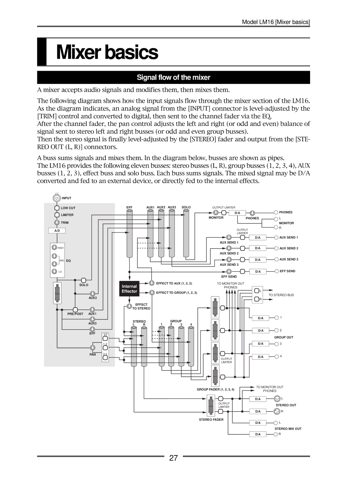
Signal flow of the mixer
A mixer accepts audio signals and modifies them, then mixes them.
The following diagram shows how the input signals flow through the mixer section of the LM16. As the diagram indicates, an analog signal from the [INPUT] connector is
After the channel fader, the pan control adjusts the left and right (or odd and even) balance of signal sent to stereo left and right busses (or odd and even group busses).
Then the stereo signal is finally
A buss sums signals and mixes them. In the diagram below, busses are shown as pipes.
The LM16 provides the following eleven busses: stereo busses (L, R), group busses (1, 2, 3, 4), AUX busses (1, 2, 3), effect buss and solo buss. Each buss sums signals. The mixed signal may be D/A converted and fed to an external device, or directly fed to the internal effects.
INPUT
![]() LOW CUT
LOW CUT
![]() LIMITER
LIMITER
![]() TRIM
TRIM
A/D
HIGH |
MID EQ |
EFF | AUX1 AUX2 AUX3 SOLO | OUTPUT LIMITER |
|
|
| D/A |
|
|
| MONITOR | PHONES |
|
| OUTPUT | |
|
| LIMITER | |
|
|
| D/A |
|
| AUX SEND 1 |
|
|
|
| D/A |
|
| AUX SEND 2 |
|
|
|
| D/A |
|
| AUX SEND 3 |
|
PHONES
L
MONITOR
R
![]()
![]() AUX SEND 1
AUX SEND 1
![]()
![]() AUX SEND 2
AUX SEND 2
![]()
![]() AUX SEND 3
AUX SEND 3
LO |
|
SOLO |
|
AUX2 |
|
PRE/POST AUX1 |
|
AUX3 |
|
EFF | ST |
| |
| |
PAN |
Internal
Effector
EFFECT
TO STEREO
STEREO
L R
EFFECT TO AUX (1, 2, 3)
EFFECT TO GROUP (1, 2, 3)
| GROUP |
| |
1 | 2 | 3 | 4 |
EFF SEND
TO MONITOR OUT
PHONES
OUTPUT
LIMITER
D/A | EFF SEND |
![]() L
L
TO STEREO BUS
![]() R
R ![]()
D/A | 1 |
D/A | 2 |
GROUP OUT
D/A | 3 |
D/A | 4 |
GROUP FADER (1, 2, 3, 4)
OUTPUT
LIMITER
STEREO FADER
![]() TO MONITOR OUT
TO MONITOR OUT
PHONES
D/A | L |
STEREO OUT
D/A | R |
D/A | L |
STEREO MIX OUT
D/A | R |
27