INSTALLATION
Wall drilling and bracket fixing
|
| 1÷2 |
7.2.1 |
| X |
|
| |
11 | 116 | 116 |
12a |
| 400 |
|
|
650 min.
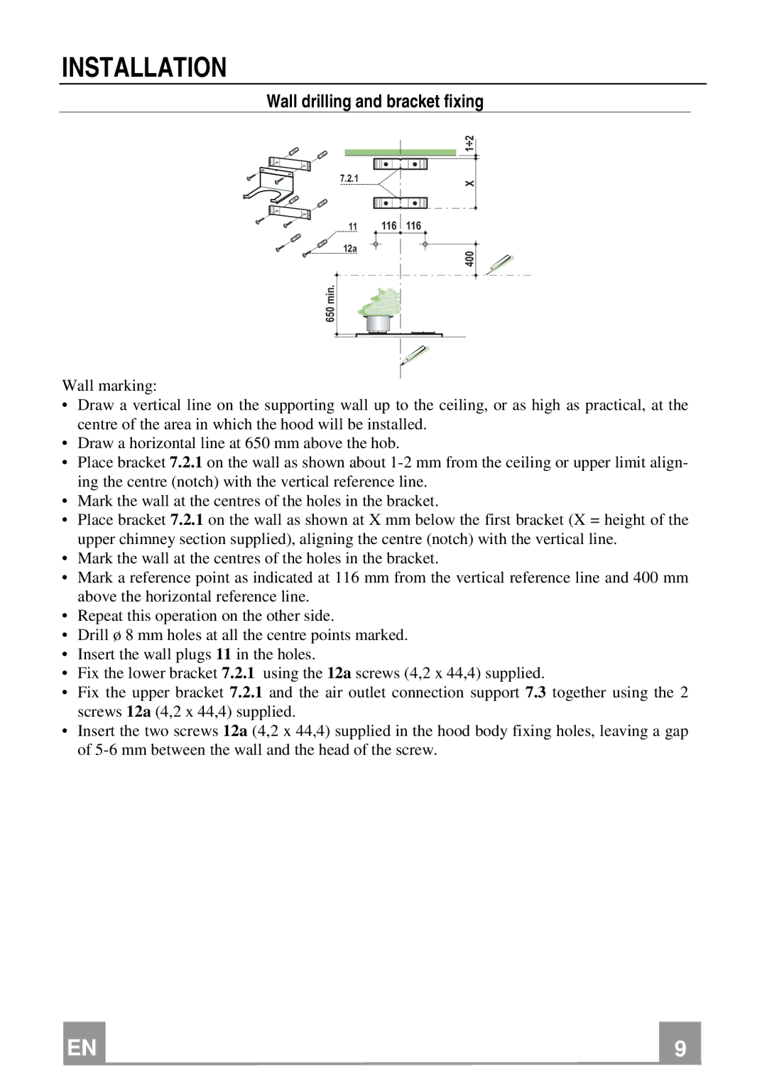
Wall marking:
•Draw a vertical line on the supporting wall up to the ceiling, or as high as practical, at the centre of the area in which the hood will be installed.
•Draw a horizontal line at 650 mm above the hob.
•Place bracket 7.2.1 on the wall as shown about
•Mark the wall at the centres of the holes in the bracket.
•Place bracket 7.2.1 on the wall as shown at X mm below the first bracket (X = height of the upper chimney section supplied), aligning the centre (notch) with the vertical line.
•Mark the wall at the centres of the holes in the bracket.
•Mark a reference point as indicated at 116 mm from the vertical reference line and 400 mm above the horizontal reference line.
•Repeat this operation on the other side.
•Drill ø 8 mm holes at all the centre points marked.
•Insert the wall plugs 11 in the holes.
•Fix the lower bracket 7.2.1 using the 12a screws (4,2 x 44,4) supplied.
•Fix the upper bracket 7.2.1 and the air outlet connection support 7.3 together using the 2 screws 12a (4,2 x 44,4) supplied.
•Insert the two screws 12a (4,2 x 44,4) supplied in the hood body fixing holes, leaving a gap of
EN |
| 9 |
| 9 |