SM18N30*, SS10N10*, SS15N30*, SS12N10*, SS14N10* specifications
Friedrich air conditioners, particularly models SS14N10*, SS12N10*, SS15N30*, SS10N10*, and SM18N30*, are renowned for their reliable performance, innovative technologies, and user-friendly features. Designed for both residential and commercial use, these units stand out due to their energy efficiency, advanced cooling capabilities, and versatile operation.One of the standout features across these models is their energy efficiency. Equipped with high SEER (Seasonal Energy Efficiency Ratio) ratings, they help users save on energy costs while reducing their carbon footprint. Specifically, the SS14N10* and SS12N10* models excel in cooling efficiency, ensuring that the spaces they occupy remain comfortably cool even in the hottest conditions. This not only contributes to lower energy bills but also promotes environmental sustainability.
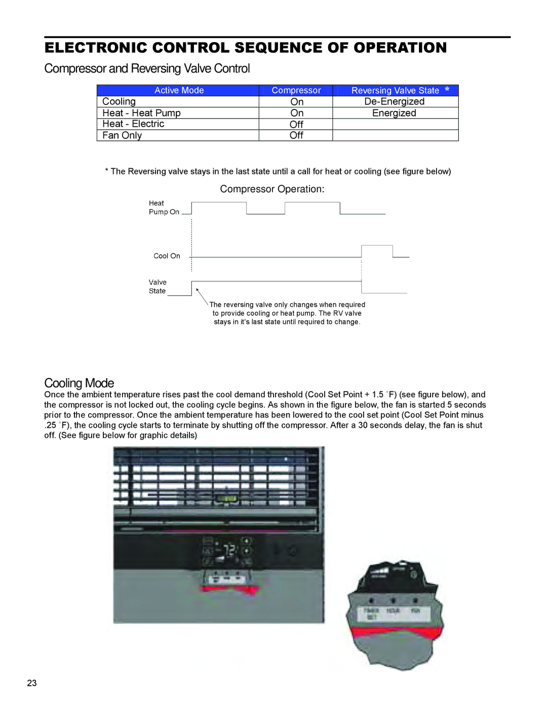
The cooling technologies integrated into these units include advanced inverter technology. This feature allows the compressor to adjust its speed according to the cooling demand of a room. As a result, these air conditioners maintain desired temperatures with minimal fluctuations, ensuring optimal comfort and significant energy savings. Models like SS15N30* and SM18N30* are particularly stellar in maintaining efficiency even during peak usage hours.
Moreover, these air conditioners are equipped with multi-stage filtration systems that enhance indoor air quality. The filters effectively capture dust, allergens, and other pollutants, resulting in cleaner and healthier air for occupants. This is especially important for individuals with allergies or respiratory issues.
User-friendly controls add another layer of convenience. Many models incorporate smart technology allowing users to control the units via mobile apps or home automation systems. This feature enables remote operation, scheduling, and real-time monitoring, making it easier to manage climate conditions effectively.
In terms of design, models like SS10N10* prioritize aesthetics without compromising functionality. They feature sleek, modern designs that seamlessly integrate into various decors, whether in a home or an office. Additionally, quiet operation technology reduces noise levels during functionality, enhancing comfort, particularly in bedrooms or quiet office environments.
Overall, Friedrich’s SS14N10*, SS12N10*, SS15N30*, SS10N10*, and SM18N30* models embody the brand's commitment to innovation and customer satisfaction. Their blend of energy efficiency, advanced cooling technology, air quality enhancement, and smart controls positions them as leaders in the air conditioning market, catering to diverse cooling needs while promoting a sustainable future.

