The main indicator of a gas or electrical circuit problem is that an entire battery of fryers fails to light. Verify that the quick disconnect fitting on the flexible gas hose is properly connected, the fryer is plugged in, and the main gas supply valve is open.
1.9.3 Problems Related to the Electrical Circuits
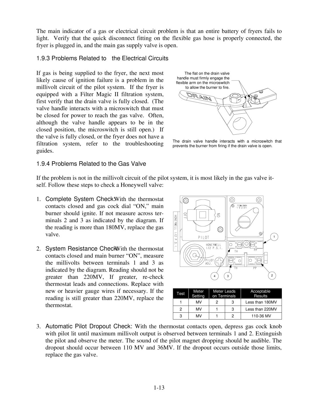
If gas is being supplied to the fryer, the next most likely cause of ignition failure is a problem in the millivolt circuit of the pilot system. If the fryer is equipped with a Filter Magic II filtration system, first verify that the drain valve is fully closed. (The valve handle interacts with a microswitch that must be closed for power to reach the gas valve. Often, although the valve handle appears to be in the closed position, the microswitch is still open.) If the valve is fully closed, or the fryer does not have a filtration system, refer to the troubleshooting guides.
1.9.4 Problems Related to the Gas Valve
The flat on the drain valve |
handle must firmly engage the |
flexible arm on the microswitch |
to allow the burner to fire. |
The drain valve handle interacts with a microswitch that prevents the burner from firing if the drain valve is open.
If the problem is not in the millivolt circuit of the pilot system, it is most likely in the gas valve it- self. Follow these steps to check a Honeywell valve:
1.Complete System Check: With the thermostat contacts closed and gas cock dial “ON,” main burner should ignite. If not measure across ter- minals 2 and 3 as indicated by the diagram. If the reading is more than 180MV, replace the gas valve.
2.System Resistance Check: With the thermostat contacts closed and main burner “ON”, measure the millivolts between terminals 1 and 3 as indicated by the diagram. Reading should not be greater than 220MV, If greater,
1
|
|
|
|
|
|
| 4 | 3 |
| 2 |
| ||||
|
|
|
|
|
|
|
|
|
|
|
|
|
|
|
|
| Test |
|
|
| Meter |
|
|
| Meter Leads |
|
|
| Acceptable |
| |
|
|
|
| Setting |
|
|
| on Terminals |
|
|
| Results |
| ||
|
|
|
|
|
|
|
|
|
|
|
| ||||
1 |
|
|
| MV |
| 2 | 3 |
|
|
| Less than 180MV | ||||
|
|
|
|
|
|
|
|
|
|
|
| ||||
2 |
|
|
| MV |
| 1 | 3 |
|
|
| Less than 220MV | ||||
|
|
|
|
|
|
|
|
|
|
|
| ||||
3 |
|
|
| MV |
| 1 | 2 |
|
|
| |||||
|
|
|
|
|
|
|
|
|
|
|
|
|
|
|
|
3.Automatic Pilot Dropout Check: With the thermostat contacts open, depress gas cock knob with pilot lit until maximum millivolt output is observed between terminals 1 and 2. Extinguish the pilot and observe the meter. The sound of the pilot magnet dropping should be audible. The dropout should occur between 110 MV and 36MV. If the dropout occurs outside those limits, replace the gas valve.