Frymaster 35 Series manual Leakage, Basket Lift Malfunctions

Models: 35 Series

1 40
Download 40 pages 11.88 Kb
Page 21
Image 21
1.9.8 Leakage

The suction tube heater and flexible hose heater are wired directly into the 24 VAC source. They remain energized as long as the unit is plugged in.

1.9.8 Leakage

Leakage of the frypot almost always will be due to improperly sealed high-limit switches, thermostats/temperature probes, and drain fittings. When installed or replaced, each of these components must be sealed with Loctite™ PST56765 sealant or equivalent to prevent leakage. In very rare cases, a leak may develop along one of the welded edges of the frypot. When this occurs, the frypot must be replaced.

If the sides and/or ends of the frypot are coated with oil, the most likely cause is spillage over the top of the frypot rather than leakage.

The clamps, which hold the drain tube sections together, may loosen over time as the tubes expand and contract during use. If the section of drain tube connected to the drain valve is removed for whatever reason, make sure that its grommet is in good condition and properly fitted around the nipple of the drain when it is reinstalled. Also, ensure that the drain tube runs downward from the drain along its whole length and has no low points where oil or shortening may accumulate.

1.9.9 Basket Lift Malfunctions

35 Series fryers may optionally be equipped with automatic basket lifts to ensure uniform cooking times. The lifts may be configured for manual control or for control via a basket lift timer. Basket lifts will always come in pairs, although each operates independently.

In units configured for manual (push-button) controls, a mechanical or electrical timer controls voltage to the system. A rotary knob is turned to set the cook time, and pressing the button in the middle of the knob activates the motor.

In units with basket-lift timers, timing circuitry in the controller initiates and stops basket-lift operation based on variables set by the operator. When the product button is pressed, the timing circuitry activates a coil in the basket lift relay to supply power to the motor.

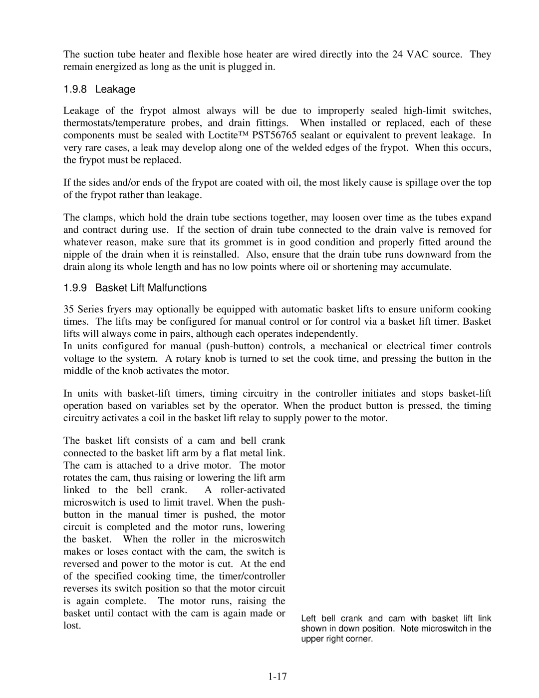
The basket lift consists of a cam and bell crank connected to the basket lift arm by a flat metal link. The cam is attached to a drive motor. The motor rotates the cam, thus raising or lowering the lift arm linked to the bell crank. A roller-activated microswitch is used to limit travel. When the push- button in the manual timer is pushed, the motor circuit is completed and the motor runs, lowering the basket. When the roller in the microswitch makes or loses contact with the cam, the switch is reversed and power to the motor is cut. At the end of the specified cooking time, the timer/controller reverses its switch position so that the motor circuit is again complete. The motor runs, raising the basket until contact with the cam is again made or lost.

Left bell crank and cam with basket lift link shown in down position. Note microswitch in the upper right corner.

1-17

Page 21
Image 21
Frymaster 35 Series manual Leakage, Basket Lift Malfunctions