The relays in earlier design boards are soldered on and cannot be replaced. Later design boards fea- ture replaceable
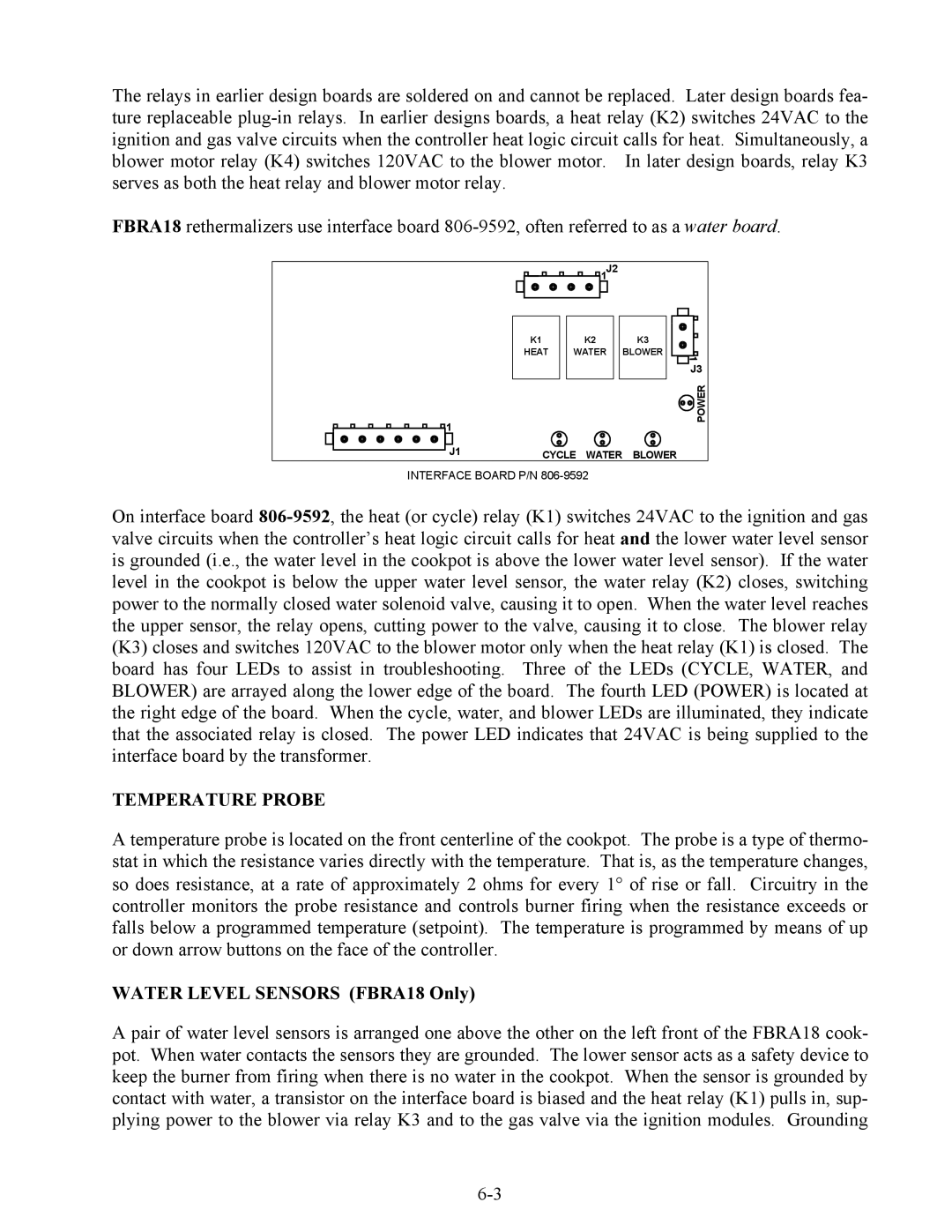
FBRA18 rethermalizers use interface board
![]()
![]()
![]()
![]()
![]() 1J2
1J2
![]()
![]()
![]()
![]()
![]() 1
1
K1 |
| K2 |
HEAT |
| WATER |
|
|
|
K3
BLOWER
![]() J3
J3
![]()
![]()
![]()
![]() POWER
POWER
J1 | CYCLE WATER BLOWER |
INTERFACE BOARD P/N
On interface board
TEMPERATURE PROBE
A temperature probe is located on the front centerline of the cookpot. The probe is a type of thermo- stat in which the resistance varies directly with the temperature. That is, as the temperature changes, so does resistance, at a rate of approximately 2 ohms for every 1° of rise or fall. Circuitry in the controller monitors the probe resistance and controls burner firing when the resistance exceeds or falls below a programmed temperature (setpoint). The temperature is programmed by means of up or down arrow buttons on the face of the controller.
WATER LEVEL SENSORS (FBRA18 Only)
A pair of water level sensors is arranged one above the other on the left front of the FBRA18 cook- pot. When water contacts the sensors they are grounded. The lower sensor acts as a safety device to keep the burner from firing when there is no water in the cookpot. When the sensor is grounded by contact with water, a transistor on the interface board is biased and the heat relay (K1) pulls in, sup- plying power to the blower via relay K3 and to the gas valve via the ignition modules. Grounding
