ITEM
PART #
COMPONENT
* Not illustrated
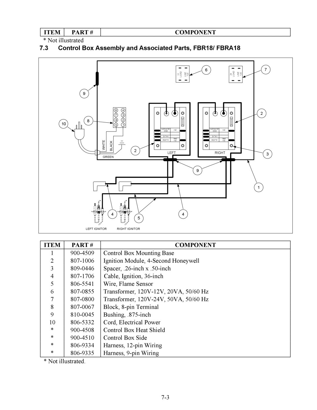
7.3Control Box Assembly and Associated Parts, FBR18/ FBRA18
|
|
|
|
|
| LOAD | 6 |
|
| LOAD | 7 |
|
|
|
|
| 12 | LINE 120 |
| 24 | LINE 120 | ||
| 9 |
|
|
|
|
|
|
|
|
|
|
|
| 8 | 4 |
|
|
|
|
|
|
| 2 |
|
| 7 | 3 |
|
|
|
|
|
|
| |
|
|
|
|
|
|
|
|
|
| ||
10 | 8 | 6 | 2 |
|
|
|
|
|
|
|
|
| 5 | 1 |
|
|
|
|
|
|
|
| |
|
|
|
| (BURNER) | 25V |
| (BURNER) | 25V |
|
|
|
|
|
|
| GND |
| GND |
|
|
| ||
|
|
|
|
|
|
|
|
|
| ||
|
|
|
| VALVE |
|
| VALVE |
|
|
|
|
| WHITE |
|
| ALARM | (GND) |
| ALARM | (GND) |
|
|
|
| BLACK |
| 25V |
| 25V |
|
|
| |||
|
|
|
|
|
|
|
| ||||
| 2 | LEFT |
| RIGHT |
|
|
| ||||
|
|
|
|
|
| 3 | |||||
| GREEN |
|
|
|
| ||||||
|
|
|
|
|
|
|
|
|
| ||
|
|
|
|
|
|
| 9 |
|
|
|
|
|
|
|
|
|
|
|
|
|
|
| 1 |
|
| 4 | 5 |
|
|
| 4 |
|
|
|
|
|
|
|
|
|
|
|
|
|
|
| |
| LEFT IGNITOR |
| RIGHT IGNITOR |
|
|
|
|
|
|
|
|
ITEM | PART # | COMPONENT |
1 | Control Box Mounting Base | |
2 | Ignition Module, | |
3 | ||
4 | Cable, Ignition, | |
5 | Wire, Flame Sensor | |
6 | Transformer, | |
7 | Transformer, | |
8 | Block, | |
9 | ||
10 | Cord, Electrical Power | |
* | Control Box Heat Shield | |
* | Control Box Side | |
* | Harness, | |
* | Harness, |
* Not illustrated.