6.2.2Logical address
(1)CHS mode
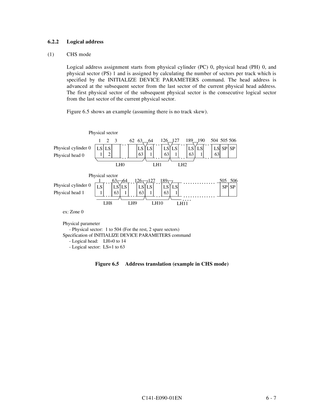
Logical address assignment starts from physical cylinder (PC) 0, physical head (PH) 0, and physical sector (PS) 1 and is assigned by calculating the number of sectors per track which is specified by the INITIALIZE DEVICE PARAMETERS command. The head address is advanced at the subsequent sector from the last sector of the current physical head address. The first physical sector of the subsequent physical sector is the consecutive logical sector from the last sector of the current physical sector.
Figure 6.5 shows an example (assuming there is no track skew).
| Physical sector |
|
| |||
Physical cylinder 0 | 1 | 2 | 3 |
| . . | |
LS | LS |
|
| |||
|
|
| ||||
Physical head 0 |
| 1 | 2 |
|
| . . |
|
|
|
|
| ||
|
|
|
|
|
| |
|
|
|
|
|
|
|
LH0
62 63 | 64 |
| . . |
| 126 | 127 | . . | 189 | 190 |
| . . |
| 504 | 505 | 506 | ||||
|
| LS | LS |
|
|
| LS | LS |
|
|
| LS | LS |
|
|
| LS | SP | SP |
|
| 63 | 1 |
| . . |
| 63 | 1 |
| . . |
| 63 | 1 |
| . . |
| 63 |
|
|
|
|
|
|
|
|
|
|
|
|
|
|
|
|
|
|
| |||
|
|
| LH1 | LH2 |
|
|
|
|
|
|
| ||||||||
| Physical sector |
|
|
|
|
|
|
|
|
|
|
|
|
|
|
|
|
|
| |||||
Physical cylinder 0 | 1 |
| . . |
| 63 | 64 |
| . . | 126 | 127 |
| . . |
| 189 |
|
| . . . . . . . . . . . . . . |
| 505 | 506 |
| |||
LS |
|
|
| LS | LS |
|
|
| LS | LS |
|
|
|
| LS | LS |
|
|
| SP | SP |
| ||
Physical head 1 |
|
|
|
|
|
|
|
|
|
|
|
|
|
|
| |||||||||
| 1 |
| . . |
| 63 | 1 |
| . . |
| 63 | 1 |
| . . |
|
| 63 | 1 |
| . . . . . . . . . . . . . . |
|
|
|
| |
|
|
|
|
|
|
|
|
|
| |||||||||||||||
|
|
| LH8 |
| LH9 | LH10 |
|
|
| . . . . |
|
|
|
| ||||||||||
|
|
|
|
| LH11 |
|
|
|
| |||||||||||||||
ex: Zone 0
Physical parameter
-Physical sector: 1 to 504 (For the rest, 2 spare sectors) Specification of INITIALIZE DEVICE PARAMETERS command
-Logical head: LH=0 to 14
-Logical sector: LS=1 to 63
Figure 6.5 Address translation (example in CHS mode)
| 6 - 7 |