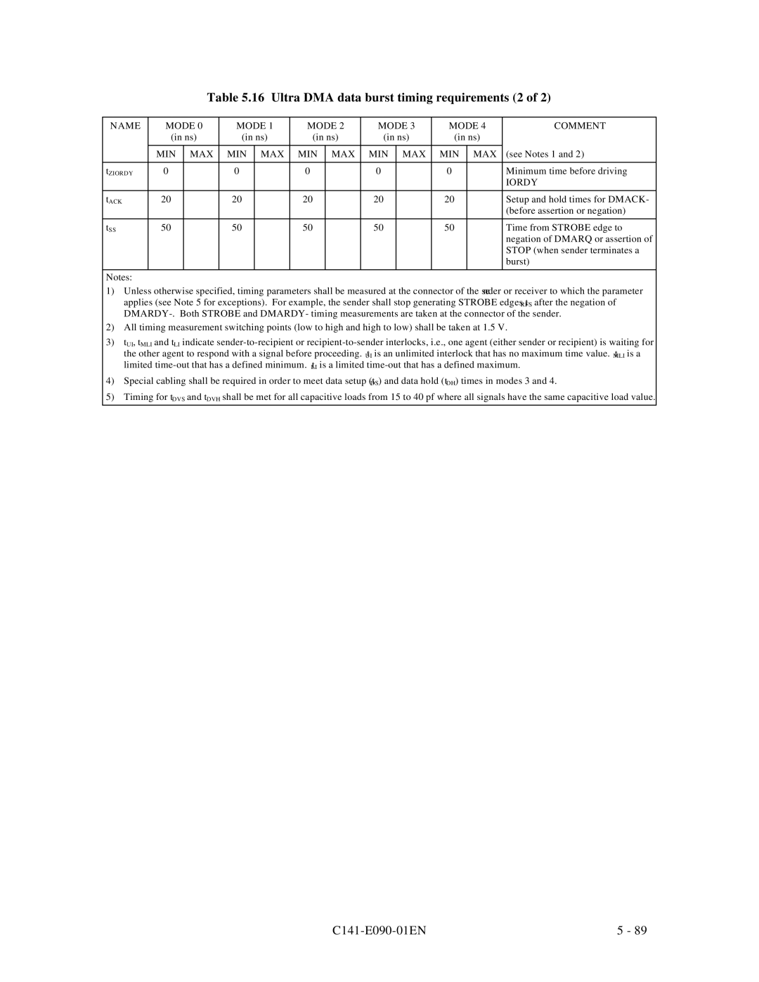
Table 5.16 Ultra DMA data burst timing requirements (2 of 2)
NAME | MODE 0 | MODE 1 | MODE 2 | MODE 3 | MODE 4 | COMMENT | |||||
| (in ns) | (in ns) | (in ns) | (in ns) | (in ns) |
| |||||
|
|
|
|
|
|
|
|
|
|
|
|
| MIN | MAX | MIN | MAX | MIN | MAX | MIN | MAX | MIN | MAX | (see Notes 1 and 2) |
|
|
|
|
|
|
|
|
|
|
|
|
tZIORDY | 0 |
| 0 |
| 0 |
| 0 |
| 0 |
| Minimum time before driving |
|
|
|
|
|
|
|
|
|
|
| IORDY |
|
|
|
|
|
|
|
|
|
|
|
|
tACK | 20 |
| 20 |
| 20 |
| 20 |
| 20 |
| Setup and hold times for DMACK- |
|
|
|
|
|
|
|
|
|
|
| (before assertion or negation) |
|
|
|
|
|
|
|
|
|
|
|
|
tSS | 50 |
| 50 |
| 50 |
| 50 |
| 50 |
| Time from STROBE edge to |
|
|
|
|
|
|
|
|
|
|
| negation of DMARQ or assertion of |
|
|
|
|
|
|
|
|
|
|
| STOP (when sender terminates a |
|
|
|
|
|
|
|
|
|
|
| burst) |
|
|
|
|
|
|
|
|
|
|
|
|
Notes: |
|
|
|
|
|
|
|
|
|
|
|
1) Unless otherwise specified, timing parameters shall be measured at the connector of the sender or receiver to which the parameter
applies (see Note 5 for exceptions). For example, the sender shall stop generating STROBE edges t after the negation of
RFS
2)All timing measurement switching points (low to high and high to low) shall be taken at 1.5 V.
3)tUI, tMLI and tLI indicate
the other agent to respond with a signal before proceeding. t is an unlimited interlock that has no maximum time value. t is a
UIMLI
limited
LI
4) Special cabling shall be required in order to meet data setup (t ) and data hold (t ) times in modes 3 and 4.
DSDH
5) Timing for tDVS and tDVH shall be met for all capacitive loads from 15 to 40 pf where all signals have the same capacitive load value.
| 5 - 89 |