Manuals
/
Fujitsu
/
Computer Equipment
/
Laptop
Fujitsu
MB9B500 Series Select a project eww file, Click “Project Rebuild All”, 5 Select a Project
Models:
MB9B500 Series
1
23
34
34
Download
34 pages
6.13 Kb
20
21
22
23
24
25
26
27
„ Flowchart
7 Press Reset Button
Hardware Setting
How to
Board Features
13 Macro File Enabled
Page 23
Image 23
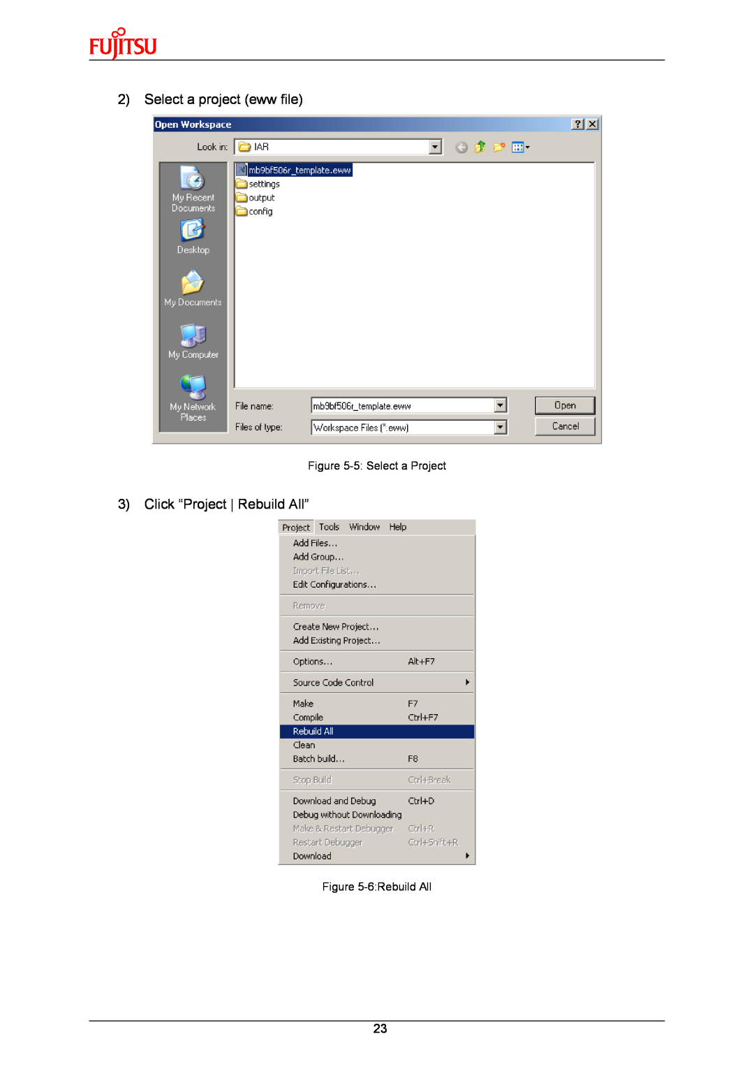
2)
Select a project (eww file)
Figure
5-5:
Select a Project
3)
Click “Project Rebuild All”
Figure
5-6:Rebuild
All
23
Page 22
Page 24
Page 23
Image 23
Page 22
Page 24
Contents
APPLICATION NOTE
FUJITSU SEMICONDUCTOR SHANGHAI LIMITED
MB9B500 Series
32-BIT MICROCONTROLLER
ALL RIGHTS RESERVED
2011-04-21
Revision History
Date
Version
3 FLASH ON-BOARD PROGRAMMING
2 HARDWARE SETTING
REVISION HISTORY
1 INTRODUCTION
1.2 MB9B506 Series MCU
1 Introduction
1.1 Product Overview
1.3 Board Features
AD channel
2 Hardware Setting
Table 2-2 Setting for UART On-Board Programming
2.3 Setting for UART On-Board Programming
2.4 Setting for USB On-Board Programming
2.2 Jumpers Overview
„ Use Keil U-Link ME
2.5 Setting for Debug Tool
„ Use IAR J-Link
3.1 On-Board Programming via UART
3 Flash On-Board Programming
Figure 3-5 COM Port in Device Manager
3.2 On-Board Programming via USB
Figure 3-7 Press Reset Button
Figure 3-4 USB Device Sign
Figure 3-8 Start Programming
„ Press reset key on the board. Programming will start
4 Sample Code
„ Usage
4.1 UART
„ Hardware Setting
„ Flowchart
Figure 4-3 Send UART Data From PC Side
Flowchart
4.2 Nand Flash
4.3 RTC
„ Hardware Setting None „ Flowchart
„ Block Diagram
4.4 CAN
4.5 USB Function
4.6 USB Host
4.7 LCD & AD & Key
Figure 5-1 J-Link Overview Figure 5-2 U-Link Overview
5 Debug Tool and IDE
Watch window Main window
5.1 Debug with J-Link in IAR EWARM Workbench
„ Run an Existed Project
Tool bar Project list Log window
Figure 5-6Rebuild All
2 Select a project eww file
3 Click “Project Rebuild All”
Figure 5-5 Select a Project
„ Setting for Flash Debug
Figure 5-11 Flash Load File Path
2 Don’t select “Use macro files” in “DebuggerSetup” table
Figure 5-10 Macro File Disabled
Figure 5-12 ICF File for RAM Debug
„ Setting for RAM Debug
2 Select “Use macro files” in “DebuggerSetup” table
Figure 5-13 Macro File Enabled
1 Use Flash debug
„ How to Make a HEX File
Figure 5-14 Flash Loader File Disabled
3 Don’t use Flash loader file
Figure 5-17 Open a Project
5.2 Debug with U-Link ME in Keil uVision4
Tool bar Project list Build output
Figure 5-16 Keil IDE Overview
Figure 5-18 Select a Project
2 Select a project uvproj file
3 Rebuild all
4 Start debug
Figure 5-21 Debug Tool Bar
Figure 5-22 ROM Address Setting for Flash Debug
Figure 5-23 Don’t use initialization File
3 Check “Update Target before Debugging” checkbox
Figure 5-24 Select Update Target Before Debugging
2 Don’t use initialization file
Figure 5-26 Select Initialization File
1 Set ROM address in Code SRAM area. 0x1fff8000-0x1fffffff
2 Set initialization file path. ..\DebugRAM.ini
Figure 5-25 Set RAM Address for RAM Debug
Figure 5-28 HEX File Generation in Keil IDE
Figure 5-27 Select Update Target Before Debugging
„ Sample code
6 Materials Download
„ Software
„ Document
Top
Page
Image
Contents