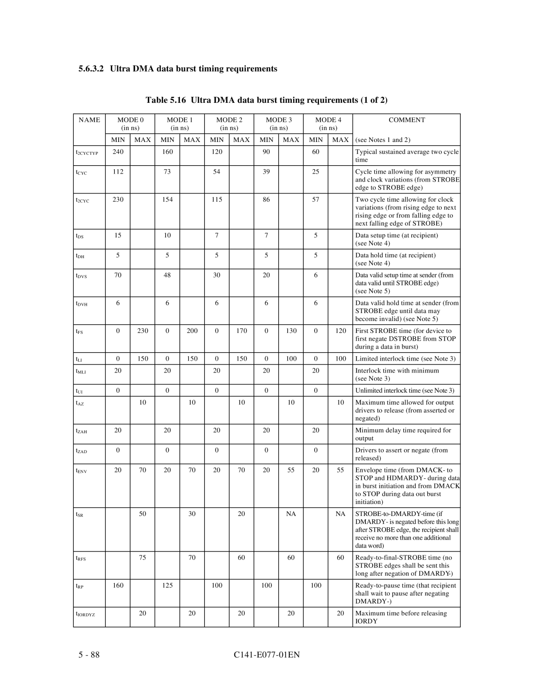
5.6.3.2 Ultra DMA data burst timing requirements

Table 5.16 Ultra DMA data burst timing requirements (1 of 2)

NAME

MODE 0

MODE 1

MODE 2

MODE 3

MODE 4

COMMENT


(in ns)

(in ns)

(in ns)

(in ns)

(in ns)


MIN

MAX

MIN

MAX

MIN

MAX

MIN

MAX

MIN

MAX

(see Notes 1 and 2)


t2CYCTYP

240


160


120


90


60


Typical sustained average two cycle


time


tCYC

112


73


54


39


25


Cycle time allowing for asymmetry


and clock variations (from STROBE


edge to STROBE edge)


t2CYC

230


154


115


86


57


Two cycle time allowing for clock


variations (from rising edge to next


rising edge or from falling edge to


next falling edge of STROBE)


tDS

15


10


7


7


5


Data setup time (at recipient)


(see Note 4)


tDH

5


5


5


5


5


Data hold time (at recipient)


(see Note 4)


tDVS

70


48


30


20


6


Data valid setup time at sender (from


data valid until STROBE edge)


(see Note 5)


tDVH

6


6


6


6


6


Data valid hold time at sender (from


STROBE edge until data may


become invalid) (see Note 5)


tFS

0

230

0

200

0

170

0

130

0

120

First STROBE time (for device to


first negate DSTROBE from STOP


during a data in burst)


tLI

0

150

0

150

0

150

0

100

0

100

Limited interlock time (see Note 3)


tMLI

20


20


20


20


20


Interlock time with minimum


(see Note 3)


tUI

0


0


0


0


0


Unlimited interlock time (see Note 3)


tAZ


10


10


10


10


10

Maximum time allowed for output


drivers to release (from asserted or


negated)


tZAH

20


20


20


20


20


Minimum delay time required for


output


tZAD

0


0


0


0


0


Drivers to assert or negate (from


released)


tENV

20

70

20

70

20

70

20

55

20

55

Envelope time (from DMACK- to


STOP and HDMARDY- during data


in burst initiation and from DMACK


to STOP during data out burst


initiation)


tSR


50


30


20


NA


NA

STROBE-to-DMARDY-time (if


DMARDY- is negated before this long


after STROBE edge, the recipient shall


receive no more than one additional


data word)


tRFS


75


70


60


60


60

Ready-to-final-STROBE time (no


STROBE edges shall be sent this


long after negation of DMARDY-)


tRP

160


125


100


100


100


Ready-to-pause time (that recipient


shall wait to pause after negating


DMARDY-)


tIORDYZ


20


20


20


20


20

Maximum time before releasing


IORDY


5 - 88

C141-E077-01EN

Page 155
Image 155
Fujitsu MPE3XXXAT manual Dmardy

MPE3XXXAT specifications

The Fujitsu MPE3XXXAT series is a robust line of hard disk drives (HDDs) known for their reliability, performance, and advanced technology. Designed primarily for enterprise storage solutions, these drives cater to high-demand environments such as data centers, servers, and workstations. With capacities ranging from hundreds of gigabytes to several terabytes, the MPE3XXXAT series offers scalable storage options to accommodate a variety of applications.

One of the standout features of the MPE3XXXAT series is its high rotational speed. With most models operating at 7200 RPM, these drives ensure faster data access and improved read/write performance. This speed makes them ideal for applications requiring quick data retrieval, such as database management and data-intensive workloads. Furthermore, the series utilizes a Serial ATA (SATA) interface, which facilitates seamless connectivity and compatibility with a wide range of systems.

The Fujitsu MPE3XXXAT series is built with advanced technologies that enhance durability and longevity. Notably, the drives incorporate advanced error correction algorithms and vibration resistance features, which are crucial for maintaining data integrity over time. This is particularly important in multi-drive environments where vibrations from one drive can affect the performance of others. The drives are also designed with low power consumption in mind, contributing to energy savings without compromising performance.

In terms of data security, the MPE3XXXAT series supports various security features that protect against unauthorized access. These include ATA security features that enable password protection and robust encryption to safeguard sensitive information from potential breaches. This aspect is particularly significant for enterprises that handle confidential data and require stringent security measures.

The operational temperature range of the MPE3XXXAT drives is optimized for demanding environments, allowing them to function effectively in a variety of conditions. Their reliability is backed by an impressive Mean Time Between Failures (MTBF), which signifies their resilience and the manufacturer's commitment to quality.

Overall, the Fujitsu MPE3XXXAT series stands out as a reliable choice for enterprise storage needs. With its blend of high speed, capacity, durability, and security features, it addresses the challenges faced by modern data centers and businesses that require efficient data management solutions. Whether for backup, archival, or active data storage, the MPE3XXXAT series is designed to deliver consistent performance and peace of mind for users.