Manuals
/
Enviro
/
Household Appliance
/
Home Security System
Enviro
EA800 Reset Button, Sensor Model No, D-011-0152, J6 Input 1 Input 2 Input 3 Input
Models:
EA800
1
28
98
98
Download
98 pages
50.46 Kb
25
26
27
28
29
30
31
32
Page 28
Image 28
Page 27
Page 29
Page 28
Image 28
Page 27
Page 29
Contents
D-011-0152
Limitations of the Alarm System or Device
Table of Contents
Installation
General Information
Preparation
Operation
General Information
Overview
How to Use This Manual
General Information
Block Diagrams
D-011-0152
Symbols on the Product or Manual Labeling
General Information
Monitoring Screens
D-011-0152
Keys
Base Unit Connections
Access Control and Passwords
will sound when an alarm occurs if DISABLE is
System Configuration Parameters
selected
Sensors
Temperature Sensors
4-20mASensors
Humidity Sensors
Theory of Operation
Power Supply / Sensor Voltage Selection
Multi-FunctionSensors
Water Sensors
Contact Closure Sensors
Sensor Parameter Descriptions
Resolution
Maximum Allowed
High Scaled Value
Relay Operation
Relay Operation
D-011-0152
Preparation
D-011-0152
From 11-26VDC power supply
To alarm-on-closed
loop circuit power supplied via loop
From 11-26VDC power supply
D-011-0152
Installation
Power Requirements
Tools and Supplies Required
Mounting the EA800 Rear Plate
EA800 Base Unit Power Connections
Install the Wired Sensors
Install the Wireless Sensors
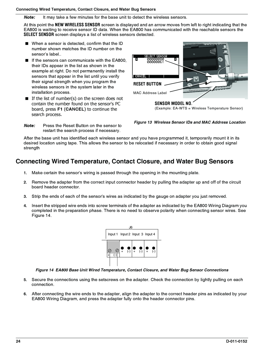
RESET BUTTON
SENSOR MODEL NO
RESET BUTTON
SENSOR MODEL NO
D-011-0152
J6 Input 1 Input 2 Input 3 Input
Connecting Wired HA-III+Humidity Sensors
Connecting Wired 4-20mASensors
Connecting the EA800 Alarm Outputs
Programming
Accessing the MAIN MENU for Programming
Configuring System Parameter Settings
3.Enter the SYSTEM menu and then select the CONFIGURATION menu as shown below
DISABLED is selected
Setting the Current Date
Setting the Time
D-011-0152
Adding Wireless Sensors
Adding a Wireless Temperature Sensor
Adding Wireless Sensors
D-011-0152
Installation
D-011-0152
D-011-0152
Installation
Adding a Wireless Humidity Sensor
D-011-0152
D-011-0152
Installation
D-011-0152
D-011-0152
Select N.O. Contact or N.C. Contact
Installation
D-011-0152
Verify Wireless Signal Strength
D-011-0152
Adding Wired Sensors
Adding a Wired Temperature Sensor
Adding Wired Sensors
Adding a Wired HA-III+Humidity Sensor
D-011-0152
Adding a Wired WaterBug Sensor
Note A supervised WaterBug sensor must be used
Select N.O. Contact or N.C. Contact
Adding a Wired Contact Closure Sensor
D-011-0152
Adding a 4-20mASensor
Configuring the Relays
Operation
Monitoring Environmental Conditions
Viewing Sensor Settings
Viewing Active Alarms
Viewing the Alarm Log
Viewing Pending Alarm Information
Viewing Limit Settings
Viewing the Event Log
Viewing the Sensor Log
Viewing Firmware Information
Operation
D-011-0152
Viewing RF Information
Viewing RF Information
Maintenance
Locking and Unlocking the EA800
Pausing Monitoring and Cancelling Pause
Adding a Sensor
Replacing a Sensor
Editing Sensor Parameters
SENSORS screen
Deleting a Sensor
Reprogramming a Relay
F3 F3
Changing the Date Format
Changing the Time Format
Changing the Date or Time Setting
Changing Sensor Data Collection Frequency
Changing the Buzzer Setting
Changing the Buzzer Setting
Maintenance
Changing the Password
D-011-0152
Clearing the Sensor Log
Clearing the Alarm Log
Clearing the Alarm Log
Maintenance
Updating the Firmware
D-011-0152
Saving Configuration Settings
F3 LOAD/SAVE CONFIG screen
Loading Configuration Settings
CONFIG screen
Exported Alarm Data
Exporting the Stored Logs
Exported Event Data
Exported Sensor Data
12/24/2007 07 06 03 PM
Sensor deleted
Exporting the Stored Logs
D-011-0152
Troubleshooting
ACTIVE ALARMS screen
Verifying RF Signal Strength
Viewing Signal Strength for a Wireless Sensor
Specifications
Base Unit and Sensor Specifications
Accessories
Appendix A Screen Maps
Figure 17. Locked Screen Map
Figure 18. Unlocked Screen Map - Top Level
D-011-0152
Figure 19. Sensors Screen Map
Appendix A Screen Maps
D-011-0152
Figure 20. Add New Sensor Screen Map
D-011-0152
Appendix A Screen Maps
Figure 21. Edit Sensor Screen Map
Figure 22. Relay Screen Map
D-011-0152
Figure 23. Data Log Screen Map
D-011-0152
Figure 24. System Screen Map
Appendix A Screen Maps
D-011-0152
Figure 25. Configuration Screen Map
D-011-0152
Appendix B Planning Worksheet
Installation
Alarm Condition
Appendix B Planning Worksheet
D-011-0152
C Wiring Diagram
Appendix
D-011-0152
Appendix D System Configuration Record
Unit of Measure
Appendix D System Configuration Record
Sensor 6 Settings wireless
Appendix D System Configuration Record
D-011-0152
Warranty and Service Information
Manufactured in the U.S.A by
Winland Electronics
1950 Excel Drive, Mankato, MN, Outside MN Phone
Phone Fax
Top
Page
Image
Contents