0+A RGB3 input terminal (RGB3 INPUT/BNC)
Connect this terminal to the PC's display (analog RGB) output terminal or decoder (digital broadcast tuner,etc.) output terminal. *When RGB3 input terminal is connected, Comp.video mode is not available. (See P.
AComponent video input terminal (VIDEO4 INPUT)
Connect this terminal to the component video output (colour difference output) terminal of your HDTV unit or DVD player. *When Comp.video input terminal is connected, RGB3 mode is not available. (See P.
BRGB3 synchronization switch (SYNC SW TTL/ANALOG (75 Ω))
This switch is used to terminate horizontal (H) terminal and vertical (V) terminal, out of RGB3 input terminals, with 75 Ω.
TTL | : Does not terminate. |
ANALOG (75 Ω): | Terminates. |
C Video1 input terminal (VIDEO1 INPUT/P-TE1000E)
Connect this terminal to the SCART terminal of your VCR or DVD, etc. *See “SETTING THE INPUT TERMINALS” on
D
E Video input terminal (VIDEO1
F Component video input terminal (VIDEO3 INPUT/P-TE1010E)
Connect this terminal to the component video output (colour difference output) terminal of your HDTV unit or DVD player.
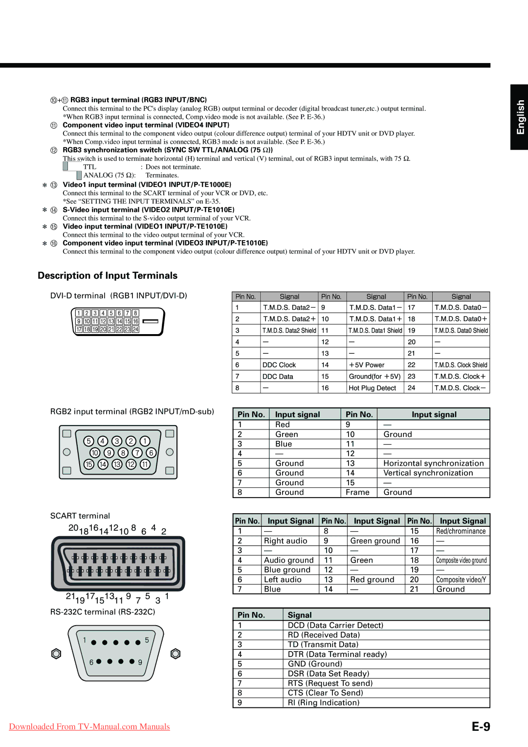
Description of Input Terminals
English
RGB2 input terminal (RGB2
SCART terminal |
|
|
201816141210 8 | 6 4 | 2 |
211917151311 9 7 5 3 1
Pin No. | Input signal | Pin No. | Input signal |
1 | Red | 9 | — |
2 | Green | 10 | Ground |
3 | Blue | 11 | — |
4 | — | 12 | — |
5 | Ground | 13 | Horizontal synchronization |
6 | Ground | 14 | Vertical synchronization |
7 | Ground | 15 | — |
8 | Ground | Frame | Ground |
Pin No. | Input Signal | Pin No. | Input Signal | Pin No. | Input Signal | |
1 | — |
| 8 | — | 15 | Red/chrominance |
2 | Right audio | 9 | Green ground | 16 | — | |
3 | — |
| 10 | — | 17 | — |
4 | Audio ground | 11 | Green | 18 | Composite video ground | |
5 | Blue ground | 12 | — | 19 | — | |
6 | Left audio | 13 | Red ground | 20 | Composite video/Y | |
7 | Blue |
| 14 | — | 21 | Ground |
|
|
|
|
|
|
|
Pin No. | Signal |
|
|
|
| |
1DCD (Data Carrier Detect)
2RD (Received Data)
3TD (Transmit Data)
4DTR (Data Terminal ready)
5GND (Ground)
6DSR (Data Set Ready)
7RTS (Request To send)
8CTS (Clear To Send)
9RI (Ring Indication)
Downloaded From |