22Page

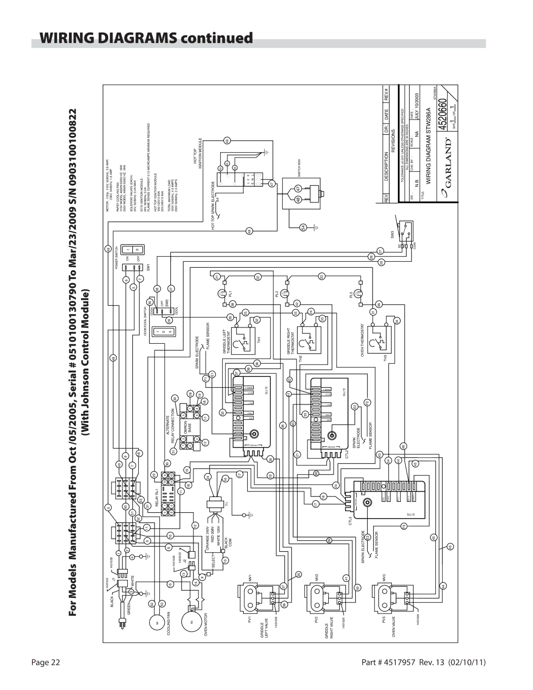
For Models Manufactured From Oct /05/2005, Serial # 0510100130790 To Mar/23/2009 S/N 0903100100822

WIRING


(With Johnson Control Module)


1431531


5


49

MOTOR: 1/3hp, 115V, 50/60Hz, 3.6 AMP,


DIAGRAMS


BLACK


J1

1431526


48


230V, 50/60Hz, 1.8 AMP


POWER SWITCH


1


49


PAPST COOLING FAN:


115V MODEL 4606N 50/60 HZ, 18W


2


50


6


6


ON

I

230V MODEL 4656N 50/60 HZ, 18W


GREEN


3

WHITE

4


51


7


SOLENOID VALVES (EACH):


5


0

24V, 50/60Hz, 0.4A MAX.


52


53


48


7

OFF


G770 IGNITION MODULE:


9

11

31


COOK/COOL SWITCH


SW1


24V, 50/60Hz, 0.2A


52


30


FLAME SENSE CURRENT 0.15 MICROAMPS MINIMUM REQUIRED


29


COOK


M~


RELAY RL1


I


28


HOT TOP IGNITION MODULE


100-120V 0.6VA


53


OFF


5

1

13

9


0


220-240V 0.8VA


30


SW2


ALTERNATE


COOLING FAN


15


8

10


II

26


27


TOTAL MAXIMUM LOAD:


8

4

14

12


RELAY CONNECTION


1431528


31

30


120V 50/60Hz, 4.5 AMPS


1434533


11


COOL


230V 50/60Hz, 2.3 AMPS


13


1

3


5


continued


J2


19

OMRON


18


2


BASE


7


29


M~


12


HOT TOP


14


4


6

8


SPARK ELECTRODE


19


IGNITION MODULE


9


OVEN MOTOR


12

11


18


F1


ORANGE 240V


24


FLAME SENSOR


SELECT


RED 208V


E1


21


HOT TOP SPARK ELECTRODE


WHITE 120V


E4


55


32


10

BLACK


16


GRIDDLE LEFT


T1


55

49


THERMOSTAT

26


PL1


COM


38


55


37


17


5


38


25


48


1

2

3


PV1


MV1


VP. 1.

V. M .3


DRNGU O

DEL

2 S H T


E S N E S


E

N

L


GRIDDLE


36

TH1

32


22


4


LEFT VALVE


20

35


G 770


47


1431526


PL2


36


37


36


41

42


GRIDDLE RIGHT


40


THERMOSTAT


25


35


21


42


48

47


TH2


SWITCH BOX


54


33


24


PV2


MV2


17


39


GRIDDLE


18


5


33


23


39


1.

3.


RIGHT VALVE


DEL

2 SHT


PV.

V. M

4ES NES


RDNGUO


24


1431526


41


CTL2


G 770


CTL3


SPARK


E2


PL3


40


GROUND


ELECTRODE


OVEN THERMOSTAT


Part


SPARK ELECTRODE


5


E3


FLAME SENSOR


F2


28


31


FLAME SENSOR


43


46


27


#


29


PV3


MV3


LED


TH3


REV


DESCRIPTION

DR.

DATE

REV.#


4517957


THS 2


34


OVEN VALVE


34


SW3


REVISIONS


P.V. 1


44


NC


TOLERANCE ±0.015" UNLESS OTHERWISE SPECIFIED


F3


46


NO


M.V. 3


ALL DIMENSIONS ARE IN INCHES


G

SENSE 4


45


COM

DR. :


CHK. BY :

SCALE :


DATE :


N.B.


NA

JULY 10/2003


1431526


077


Rev.


TITLE:


WIRING DIAGRAM STW286A


45


4520660STW286A


13


44


(02/10/11)


43


SHT 1


1


OF


Page 22
Image 22
Garland STW286A operation manual With Johnson Control Module

STW286A specifications

The Garland STW286A is a versatile and robust commercial waffle maker designed to meet the demands of busy kitchens, whether they are in restaurants, cafes, or food trucks. This countertop unit is engineered for efficiency and ease of use, ensuring that operators can produce high-quality waffles consistently and quickly.

One of the key features of the Garland STW286A is its dual waffle cooking capability. It can produce two waffles simultaneously, significantly enhancing production speed during peak hours. The unit is designed to accommodate standard Belgian-style waffles, allowing for an appealing and familiar product that customers love. The cooking plates are constructed from heavy-duty cast iron, which not only aids in heat retention but also contributes to the even cooking of the waffles, delivering a perfect golden brown finish every time.

The Garland STW286A is equipped with advanced temperature control technology that provides accurate heat distribution across the cooking surface. This feature ensures that regardless of how many waffles are being made in a session, each one will have the same texture and consistency, minimizing the risk of undercooking or overcooking. Additionally, the unit's adjustable thermostat allows operators to tailor the cooking temperature based on the recipe or desired level of crispness, offering flexibility to cater to various preferences.

Safety is a priority in the design of the STW286A. The unit features cool-touch handles, which not only protect users from burns but also provide ease of handling during operation. Moreover, the waffle maker is equipped with rubber feet to ensure stability and prevent slipping on countertops during use, maintaining safety in a fast-paced environment.

Cleaning and maintenance are made simple with the Garland STW286A. The non-stick coating on the waffle plates means that food release is effortless, and any residue can be wiped away quickly, allowing for rapid turnover between different waffle batches. Additionally, the unit's design includes a removable drip tray that captures excess batter and ensures the workspace remains tidy.

In summary, the Garland STW286A is an ideal choice for commercial establishments that aim to deliver delicious waffles efficiently. With features such as dual cooking surfaces, advanced temperature control, safety-focused design elements, and easy maintenance, it caters to both the operational needs of kitchens and the culinary preferences of customers. Whether for breakfast menus or dessert selections, this waffle maker stands out as a reliable addition to any food service operation.