Magnum 6KM Mobile Ethernet Switch Installation and User Guide | 07/10 |
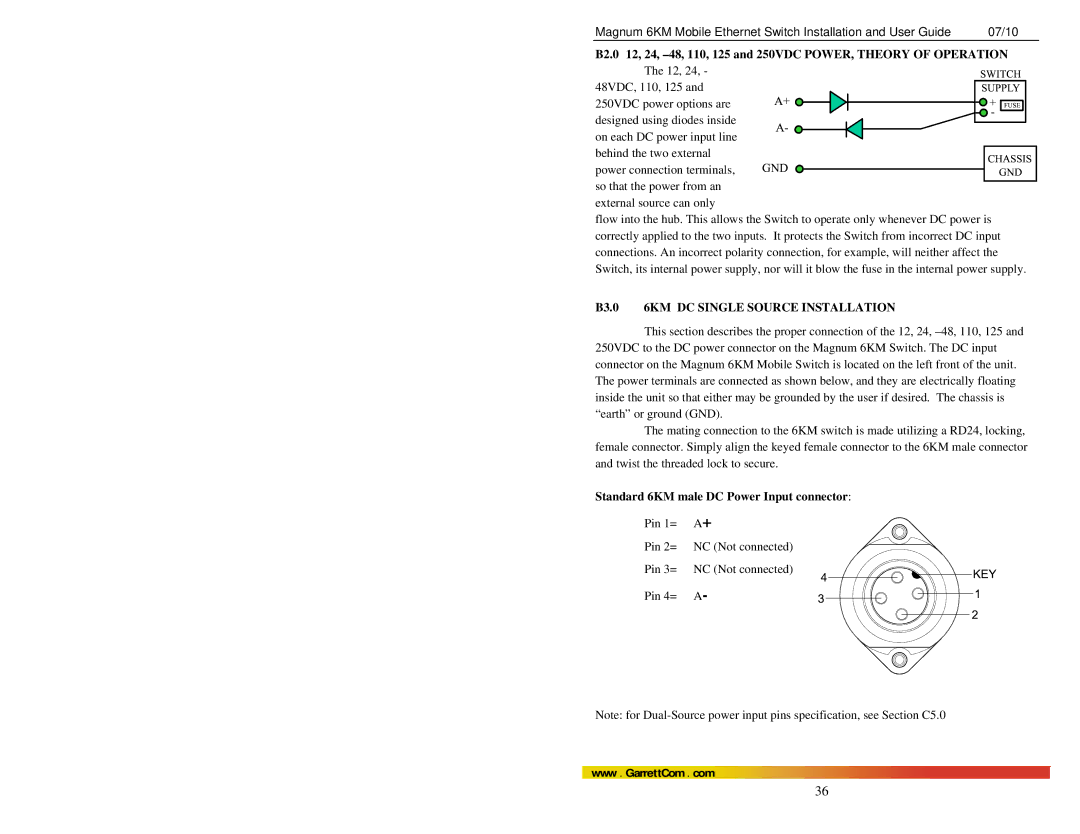
B2.0 12, 24, ![]()
![]()
![]()
48VDC, 110, 125 and 250VDC power options are designed using diodes inside
on each DC power input line behind the two external
power connection terminals, so that the power from an
external source can only
flow into the hub. This allows the Switch to operate only whenever DC power is correctly applied to the two inputs. It protects the Switch from incorrect DC input connections. An incorrect polarity connection, for example, will neither affect the Switch, its internal power supply, nor will it blow the fuse in the internal power supply.
B3.0 6KM DC SINGLE SOURCE INSTALLATION
This section describes the proper connection of the 12, 24,
The mating connection to the 6KM switch is made utilizing a RD24, locking, female connector. Simply align the keyed female connector to the 6KM male connector and twist the threaded lock to secure.
Standard 6KM male DC Power Input connector:
Pin 1= A+
Pin 2= NC (Not connected)
Pin 3= NC (Not connected)
Pin 4= A-
Note: for
www . GarrettCom . com
36