connecting the breaker from all power sources, per- form the following procedure:
1.Check that all phase sensors are the same type (current range).
2.Verify that the tap settings on all three phase sen- sors are identical.
3.Verify that the wiring harness connections to the sensors have the proper polarity (white lead to common, black lead to tap), as shown in the cabling diagram in Figure 36.
4.On ground fault breakers serving
a.Verify that the neutral sensor has the same rat- ing and tap setting as the phase sensors.
b.Verify continuity between the neutral sensor and its
c.If the breaker’s lower studs connect to the power source, then the neutral sensor must have its load end connected to the source.
d.Verify that the neutral conductor is carrying only the neutral current associated with the breaker’s load current (the neutral is not shared with other loads).
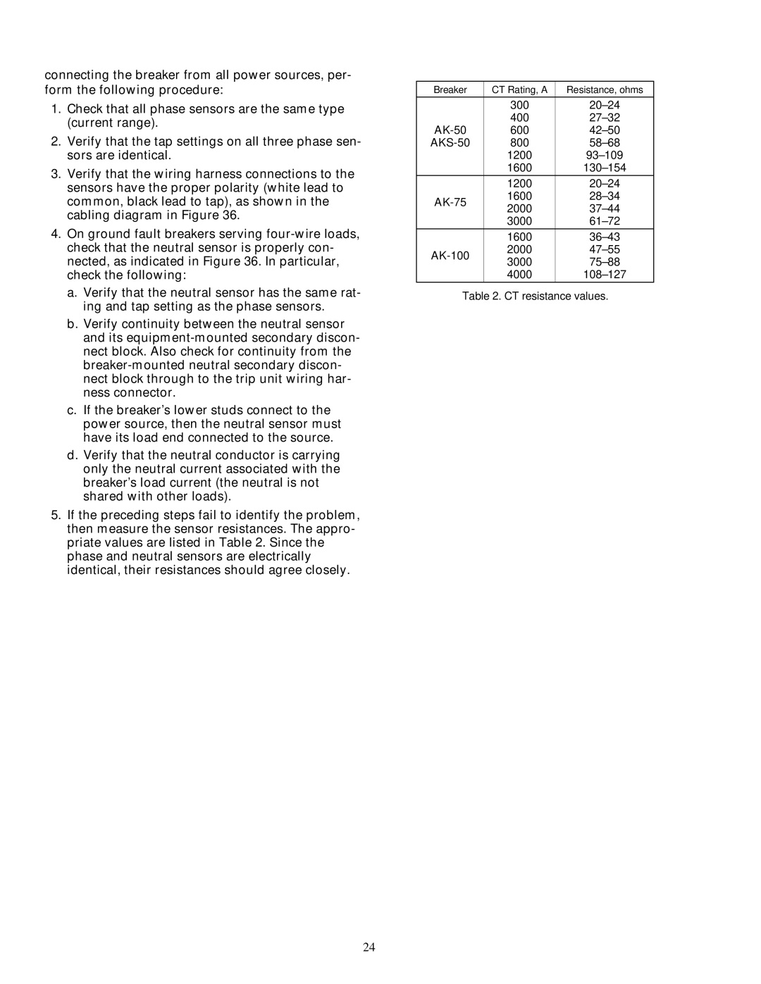
5.If the preceding steps fail to identify the problem, then measure the sensor resistances. The appro- priate values are listed in Table 2. Since the phase and neutral sensors are electrically identical, their resistances should agree closely.
Breaker | CT Rating, A | Resistance, ohms | |
|
|
| |
| 300 | ||
| 400 | ||
| 600 | ||
800 | |||
| 1200 | ||
| 1600 | ||
| 1200 | ||
1600 | |||
2000 | |||
| |||
| 3000 | ||
| 1600 | ||
2000 | |||
3000 | |||
| |||
| 4000 |
Table 2. CT resistance values.
24