SECTION 4. BACK FRAME
CONVERSION
The back frame conversion consists of the following operations:
1.Modification of the crossbar assembly for the flux shifter installation.
2.Removal of the existing trip devices.
3.Installation of the phase sensors.
4.Installation of the back frame harness.
Crossbar Modification
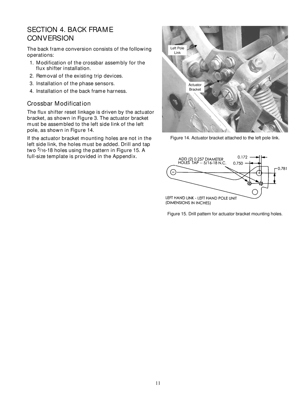
The flux shifter reset linkage is driven by the actuator bracket, as shown in Figure 3. The actuator bracket must be assembled to the left side link of the left pole, as shown in Figure 14.
If the actuator bracket mounting holes are not in the left side link, the holes must be added. Drill and tap two
Left Pole
Link
Actuator
Bracket
Figure 14. Actuator bracket attached to the left pole link.
Figure 15. Drill pattern for actuator bracket mounting holes.
11