Breakers with ECS or SST Trip Systems
1.Remove the ECS or SST trip unit.
2.Remove the existing flux shifter device and the trip unit control harness.
3.Install the new flux shifter assembly as described above and shown in Figure 5.
Installing the Trip Paddle
For breakers equipped with an ECS or SST trip sys- tem, the existing trip paddle is used with the new flux shifter.
For all other breakers, the existing trip paddles must be removed and the new trip paddle installed as follows:
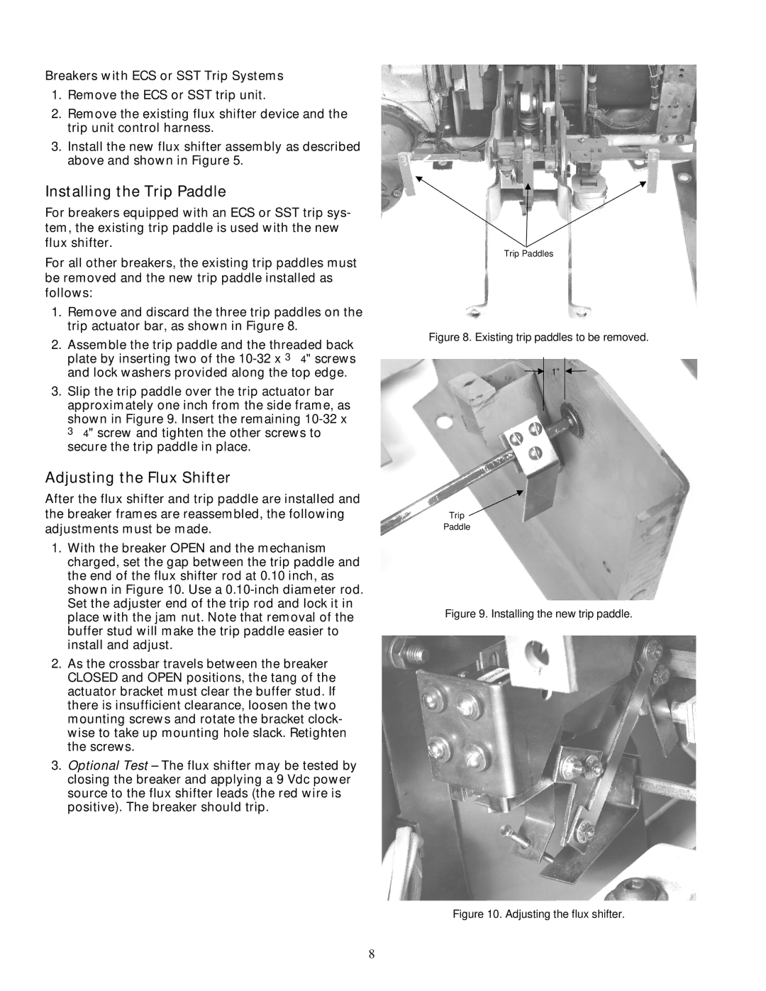
1.Remove and discard the three trip paddles on the trip actuator bar, as shown in Figure 8.
2.Assemble the trip paddle and the threaded back plate by inserting two of the
3.Slip the trip paddle over the trip actuator bar approximately one inch from the side frame, as shown in Figure 9. Insert the remaining
Adjusting the Flux Shifter
After the flux shifter and trip paddle are installed and the breaker frames are reassembled, the following adjustments must be made.
1.With the breaker OPEN and the mechanism charged, set the gap between the trip paddle and the end of the flux shifter rod at 0.10 inch, as shown in Figure 10. Use a
2.As the crossbar travels between the breaker CLOSED and OPEN positions, the tang of the actuator bracket must clear the buffer stud. If there is insufficient clearance, loosen the two mounting screws and rotate the bracket clock- wise to take up mounting hole slack. Retighten the screws.
3.Optional Test – The flux shifter may be tested by closing the breaker and applying a 9 Vdc power source to the flux shifter leads (the red wire is positive). The breaker should trip.
Trip Paddles
Figure 8. Existing trip paddles to be removed.
1”
Trip
Paddle
Figure 9. Installing the new trip paddle.
Figure 10. Adjusting the flux shifter.
8