HARDWARE
3. HARDWARE
3.1.MODULE DESCRIPTION
Serial CAN BUS
DIGITAL
I/O
DIGITAL
I/O
Optional
Power Supply
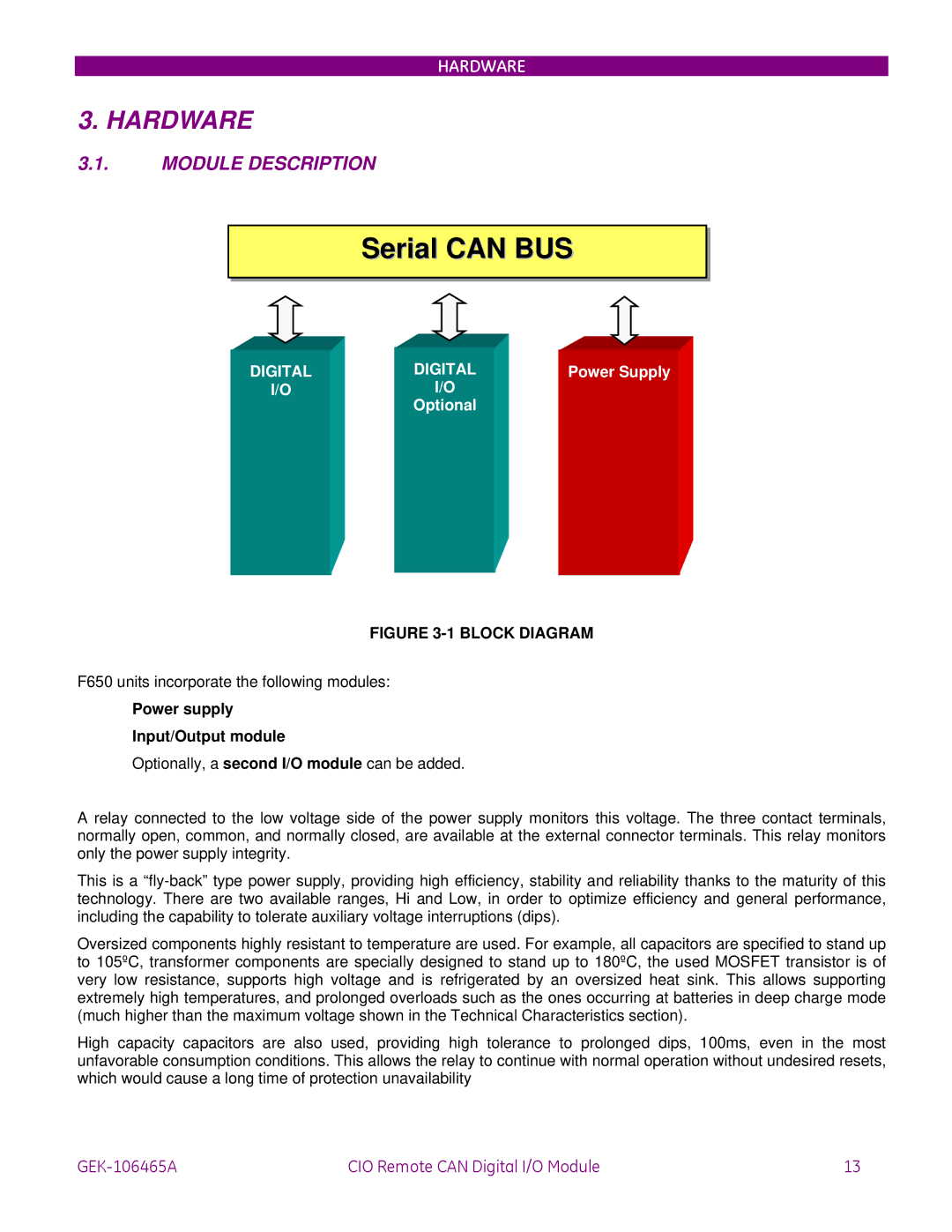
FIGURE 3-1 BLOCK DIAGRAM
F650 units incorporate the following modules:
Power supply
Input/Output module
Optionally, a second I/O module can be added.
A relay connected to the low voltage side of the power supply monitors this voltage. The three contact terminals, normally open, common, and normally closed, are available at the external connector terminals. This relay monitors only the power supply integrity.
This is a
Oversized components highly resistant to temperature are used. For example, all capacitors are specified to stand up to 105ºC, transformer components are specially designed to stand up to 180ºC, the used MOSFET transistor is of very low resistance, supports high voltage and is refrigerated by an oversized heat sink. This allows supporting extremely high temperatures, and prolonged overloads such as the ones occurring at batteries in deep charge mode (much higher than the maximum voltage shown in the Technical Characteristics section).
High capacity capacitors are also used, providing high tolerance to prolonged dips, 100ms, even in the most unfavorable consumption conditions. This allows the relay to continue with normal operation without undesired resets, which would cause a long time of protection unavailability
CIO Remote CAN Digital I/O Module | 13 |