7227946 215C1044P015 49-5006108-00 JR
Water Softening system
Two easy ways to register your appliance
GE & You, a Service Partnership
Safety Precautions
Unpacking and Inspection
Installation instructions
Important Installation Recommendations
See Where to Install the Softener section for more details
Where to Install the Softener
Plan How You Will Install the Softener
Tools and Materials Required for Installation
Optional 3-Valve Bypass Installation Illustration
Typical Installation Illustration
Plumb in and OUT Pipes to and from Softener
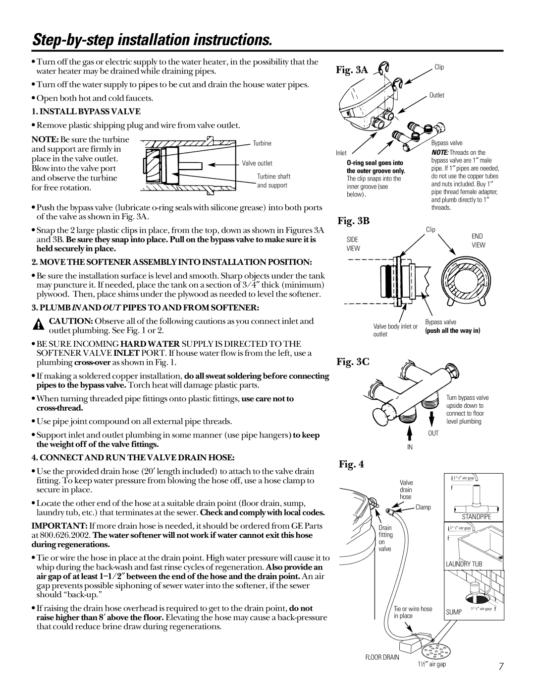
Step-by-step installation instructions
Install Bypass Valve
Move the Softener Assembly Into Installation Position
ADD Water and Salt to the Brine Tank
4A. Connecting a Rigid Valve Drain Tube
Install the Brine Tank Overflow Fittings and Hose
Connect to Electrical Power
SET Regeneration Starting Time
Programming the Control
SET Present Time of DAY Present Time
SET Water Hardness Number
SPECIFICATIONS/DIMENSIONS GXSF27 GNSF35 GXSF39
Sanitizing Procedures
About the water softener system
Breaking a Salt Bridge
Cleaning the Nozzle and Venturi Assembly
Cap
Normal Operation, Control Displays
Feature Optional Recharge Controls
Feature Program Memory
Feature/Service Automatic Electronic Diagnostics
To remove an error code 1 Unplug transformer
Service Timer/Softener, Service Checkout Procedure
ERR
SR31
SR22
SR35
If the water softening system does not draw brine, check
Care and cleaning of the water softening system
Cleaning Iron Out of the Water Softening System
Checking the Salt Storage Level and Refilling
Problem Possible Causes What To Do No soft water
Before you call for service…
That does not mix soft and hard water
Water feels slippery
After installation Water softening system
Not using any salt
After installation
Water has air bubbles
Is cloudy Error Code on control
Resin beads showing
Up in drinking water Sink Sounds you might hear
Parts list
153
Parts catalog
Housing Sensor
Switch
NUT Installation
Tube Installation
For The Period We Will Replace
What Is Not Covered
Warrantor General Electric Company. Louisville, KY
GE Water Softening System Warranty For Customers in Canada
Page
La section Française
Directives d’installation
Conserver Soigneusement
Vous et GE, un partenariat de service
Avertissement
Recommandations importantes pour l’installation
Directives d’installation
Déballage et inspection
Où installer l’adoucisseur
Planifiez comment vous allez installer l’adoucisseur
Outillage et matériel requis pour l’installation
’EAU
Illustration d’une installation type
Raccordez ET Faites Fonctionner LE Tuyau DE Vidange
Directives d’installation étape par étape
Installez LE Clapet DE Dérivation
SUR L’ORIFICE D’ENTRÉE DU Clapet DE L’ADOUCISSEUR
Programmation DU Panneau DE Commande
Installation D’ATTACHES DE Mise À LA Masse ET Câblage
’INSTALLATION Pour Détecter LES Fuites D’EAU
Ajout DE L’EAU ET DU SEL AU Réservoir DE Solution Saline
Programmation DE L’HEURE DE Régénération Début
Programmation du panneau de commande
Affichage DE L’HEURE Actuelle Present Time
Affichage DE LA Dureté DE L’EAU
SPÉCIFICATIONS/DIMENSIONS GXSF27 GNSF35 GXSF39
Pour terminer l’installation, suivez la méthode suivante
Méthode de sanitization
Au sujet du système adoucisseur d’eau
Nettoyage de l’ensemble gicleur et venturi
Élimination d’un pont de sel
Exemples
Particularités Commandes pour recharge optionnelle
Affichages en utilisation normale
Particularité Mémoire du programme
Rectifiez l’anomalie Branchez le transformateur
PAS D’EAU Traitée
Tous les réglages de codes
Service Diagnostics manuels initiés manuellement
Élimination du fer dans le système adoucisseur d’eau
Service Vérification de l’avance manuelle de régénération
Si l’adoucisseur n’aspire pas la solution saline, vérifiez
Entretien et nettoyage du système adoucisseur d’eau
Problème Causes possibles Correctifs Pas d’eau traitée
Avant d’appeler un réparateur…
’eau ne consomme
Après l’installation
Parfois, l’eau est dure
’eau, l’eau paraît Être « glissante »
Erreur de code sur
’eau a un goût salé
Il y a des bulles dans
’eau qui est trouble
Liste des pièces
153
Catalogue des pièces
Attache DE Tuyau
Bouchonrégulateurde DÉBIT,COMMANDEDERINÇAGE
Écrou D’INSTALLATION
Tube D’INSTALLATION
Page
Trois ans
Pour la période de Nous remplacerons
Ce qui n’est pas couvert
Un an
GE Answer Center Aux États-Unis
Numéros de téléphone pour le service
Instrucciones de instalación
La sección Español
Escriba los números de modelo y serie aquí
Guarde los recibos de venta o los cheques cancelados aquí
GE & Usted, Una Asociación de Servicio
¡Dos formas fáciles de registrar su electrodoméstico
De usar exclusivamente el transformador incluido
Precauciones DE Seguridad
Desempacado e inspección
Instrucciones de instalación
Recomendaciones importantes para la instalación
Dónde instalar el descalcificador
Planifique cómo instalará el descalcificador
Herramientas y materiales necesarios para la instalación
Ilustración de la instalación de un bypass de 3 válvulas
Ilustración de instalación típica
Instale LA Válvula DE Bypass
Instrucciones de instalación paso por paso
4A. Conectando UN Tubo DE Drenaje DE Válvula Rígida
Notas
Programación del Control
Procedimientos de desinfección
ESPECIFICACIONES/DIMENSIONES GXSF27 GNSF35 GXSF39
Acerca del sistema de descalcificación de agua
Limpiando la ensambladura de la boquilla y el Venturi
Rotura de un puente de sal
Ejemplos
Operación normal, pantalla de control
Característica Controles opcionales de recargado
Característica Memoria del programa
Posible Defecto
Haga Todos los ajustes del sincronizador
Servicio Diagnóstico electrónico iniciado manualmente
Servicio Inspección manual del avance de la regeneración
Cuidado y limpieza del sistema de descalcificación de agua
Antes de llamar para solicitar servicio…
Problema Posible causa Qué hacer No hay agua
Descalcificada
De agua no está Usando ninguna
Problema Posible causa Qué hacer Veces el agua
Está dura
El agua se siente
Escuchar El agua tiene
Problema Posible causa Qué hacer Las partículas
Agua y está Turbia Un error de
Usted puede
Lista de partes
153
Catálogo de partes
Cubierta DE LA Válvula
Espaciador
Interruptor
Pasador DE Expansión
Por el período de Nosotros remplazaremos
Garantía GE para el Sistema de Descalcificación de Agua
Lo que no está cubierto
Notas
Notas
TDD-GEAC
Números Telefónicos de Servicio
U.S., call 800-TDD-GEAC Canada, contact
Service Telephone Numbers